


Make Electrical Connections
POWER SUPPLY — Electrical characteristics of available
power supply must agree with unit nameplate rating. Supply
voltage must be within the limits shown in Table 5.
Field Wire Routing — Field wiring is brought into the unit
through the bottom of the control box.
A3
5
⁄
8
-in. hole for field power wiring and a
7
⁄
8
-in. hole for
24-v control wiring are provided in the bottom of the control
box. Field-supplied couplings must be used when routing wir-
ing into the control box.
Field Electrical Connections
IMPORTANT: The 48/50MP units generate, use, and
can radiate radio frequency energy. If units are not in-
stalled and used in accordance with these instructions,
they may cause radio interference.They have been tested
and found to comply with limits of a Class A com-
puting device as defined by FCC (Federal Communi-
cations Commission) regulations, Subpart J of Part 15,
which are designed to provide reasonable protection
against such interference when operated in a commer-
cial environment.
POWER WIRING — Units are factory wired for 460-v as
shown on the unit nameplate. The main terminal block is
suitable for use with aluminum or copper wires. Maximum
wire size is 500 MCM.
Branch circuit for power supply to unit must be protected
against ground fault or short circuit. Provide an overcurrent
protection device in the branch circuit. The MOCP (Maxi-
mum Overcurrent Protection) value for this device is shown
on unit informative data plate.
When installing units, provide and install a unit safety dis-
connect per NEC of adequate size. Refer to Electrical Data
tables for disconnect sizing.Disconnect may incorporate branch
circuit fusing (if local or national codes permit) but combi-
nation disconnect fuse is not required. Disconnect must be
able to be locked OFF.
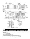
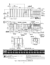
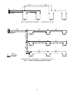
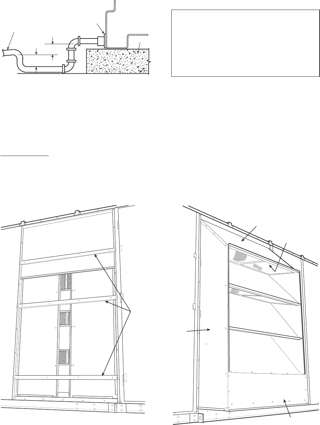
PITCH DRAIN LINE
TO OFFSET LINE
FRICTION
7" MIN.
2" MIN.
SEALANT
SLAB
UNIT
BASE
RAIL
SLAB MOUNT DRAIN
Fig. 9 — Condensate Drain Piping Details
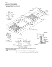
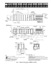
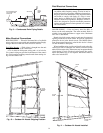
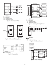
HOLD
DOWN
BARS
Fig. 10 — Outdoor Air Hoods Shipping Position
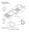
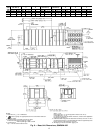
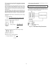
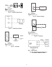
HOOD
SIDE
HOOD
TOP
FILTER
RACK
BLOCK-OFF
PLATE
Fig. 11 — Outdoor Air Hoods Installed
14