


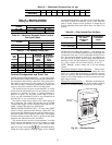
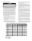
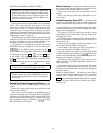
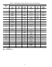
Table 25 — Basic Configuration Data
SET POINT SUBFUNCTION DISPLAY DEFAULT RANGE
Unit Type
TYPE 1 = VAV CV = 0, VAV = 1
CV Fan Mode
FANM 1 (Continuous) Auto = 0, Cont = 1
Economizer Minimum
Damper Position
MDP 20 percent 0 to 100
Heating Occupied*
OHSP 68 (F) 55 to 80
Cooling Occupied
OCSP 78 (F) 55 to 80
Cooling Unoccupied
UCSP 90 (F) 75 to 95
Heating Unoccupied
UHSP 55 (F) 40 to 80
Static Pressure
SPSP 1.5 (in. wg) 0 to 5.0
Supply Air Temperature
SASP 55 (F) 45 to 70
Date and Time
TIME dow.hh.mm mm.dd.yy —
Override Schedules†
OVRD x HR 0 (hrs) 0, 1, 2, 3 or 4
Schedule I Periods
OCC HH.MM — —
LEGEND
CV — Constant Volume
VAV — Variable Air Volume
*Requires Occupied Heating function enabled.
†See text section for discussion and instructions.
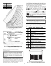
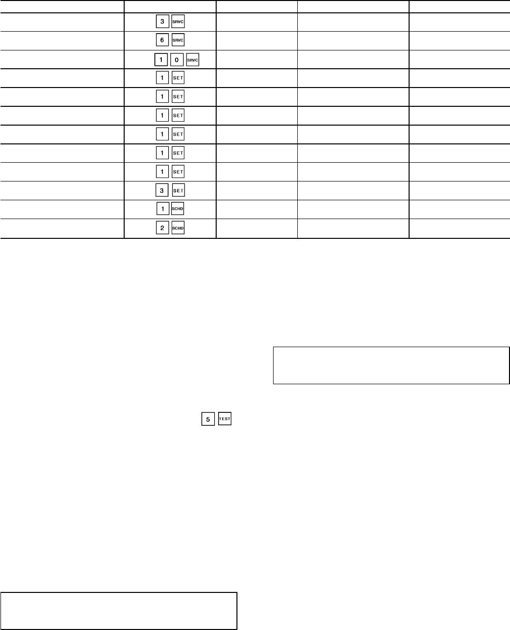
Gas Pressure Check — Prior to performing the Quick
Test, install gas pressure gages and jumper as follows:
1. Turn off manual gas stop valve.
2. Install a jumper between HR1-NO and HR2-NO.
3. Connect pressure gage to gas supply pressure tap. See
Fig. 34.
4. Connect pressure gage to manifold pressure tap on each
gas manifold.
5. Turn on manual gas stop valve.
During the heating portion of the Quick Test, ,
both the first and second stage of gas heat will be tested.
During the first stage, all of the burner sections will operate
at low fire condition (approximately 75% capacity). During
the second stage, all of the burner sections will operate at
100% capacity.
During the Quick Test of stage 2, after the unit has been
operating for several minutes, verify that the incoming gas
line pressure is 5.5 in. wg or greater. Also, verify that the
manifold pressure at each burner section is 3.3 in. wg. If
manifold pressure must be adjusted, refer to the Gas Valve
Adjustment section on page 52.
After the unit has been in operation for 5 minutes, check
the temperature rise across the unit heat exchangers. See the
unit informative plate for correct rise range limits. Air quan-
tities may need to be adjusted to bring the actual rise within
allowable limits.
IMPORTANT: After the Quick Test has been perfor-
mend for stage 2, remove the jumper betwen HR1-NO
and HR2-NO.
Check Supply Fan Rotation — If unit is equipped
with an optional VFD, check for correct fan rotation. Fan
direction can be changed by disconnecting power and switch-
ing 2 power leads downstream of the VFD output terminals
T1, T2, and T3.
START-UP
Initial Check
IMPORTANT: Do not attempt to start unit, even mo-
mentarily, until all items on the Start-Up Checklist and
the following steps have been completed.
1. Verify unit has been installed per the Installation section
of this literature.
2. Certify that all auxiliary components (sensors, controls,
etc.) have been installed and wired to the control boxes
per these instructions, the Controls and Troubleshooting
literature and the unit wiring label diagrams.
3. Verify that pressure hoses (static, duct, etc.) are properly
attached, routed, and free from pinches or crimps that may
affect proper control operation.
4. Set any control configurations that are required (field-
installed accessories, etc.). The unit is factory configured
for all appropriate factory-installed options with the
applicable controls programmed to the default values. See
unit Controls and Troubleshooting literature for appli-
cable configuration values.
5. Enter unit set points (if applicable). The unit is shipped
with the set point default values shown in the Con-
trols and Troubleshooting literature. If a different set point
is required, change per the example shown under Set
Point Function section in Controls and Troubleshooting
literature.
6. Configure schedule subfunctions (if applicable): occu-
pied, unoccupied, and holiday periods. See Schedule Func-
tion section in Controls and Troubleshooting literature for
details on setting periods.
7. Verify that control time periods programmed meet cur-
rent requirements.
8. Check all electrical connections to be sure they are tight.
38