


9
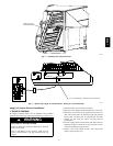
The smoke detector contains a photoelectric detector approved
for an extended air speed range of 100 to 4000 feet per minute
and an operational temperature range of -4_ to 158_F. Do not
operate the smoke detector out of these ranges.
The smoke detector operates on 24 vac, 120 vac, or
220/240 vac. The thermostat power terminals on the unit are used
to power the smoke detector.
The cover of the controller contains the Alarm, Trouble, Dirty
and Power LEDs. The cover of the sensor contains the Alarm,
Trouble and Power LEDs. (See Fig 2.)
The smoke detector can be reset by a momentary power
interruption, by the reset button on the front cover, by the control
pane l, or by the remote reset accessory.
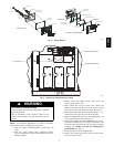
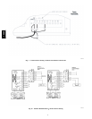
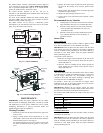
RETURN SENSOR
CONTROL MODULE
SECURE FROM BEHIND
WITH SCREW
J1
S
E
J1
J2
S
E
RETURN SENSOR
J1
J2
CONTROL MODULE
J1
TERMINAL STRIP
C07182
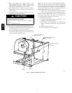
Fig. 11 --- Sensor Installation
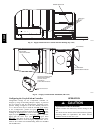
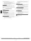
Airflow
HVAC duct
Sampling
tube
Retainer
clip
Optic
plate
Optic
housing
Sensor
housing
C07183
Fig. 12 --- Sensor Cleaning Diagram
MAINTENANCE
IMPORTANT: Notify the pr oper a uthorities that the smoke
detector system is undergoing maintenance, and that the system
will temporarily be out of service. Disable the zone or system
undergoing maintenance to prevent unwanted alarms and
possible dispatch of the fire department.
Cleaning Procedure
1. Disconnect power from the duct detector then remove the
sensor’s cover.
2. Using a vacuum cleaner, clean compressed air , or a soft
bristle brush, remove loose dirt and debris from inside the
sensor housing and cover. (See Fig 12.)
Use isopropyl alcohol and a lint-free cloth to remove di rt
and other contaminants from the gasket on the sensor’s
cover.
3. Squeeze the retainer clips on both sides of the optic hous-
ing then lift the housing away from the printed circuit
board.
4. Gently remove dirt and debris from around the optic plate
and inside the optic housing.
5. Replace the optic housing and sensor cover.
6. Connect power to the duct detector then perform a sensor
alarm test.
Recommended Service Schedule
S
V isually inspect each sensor connected to the controller
upon installation and once every 6 months thereafter.
S Perform a sensor alarm test on each sensor connected
to the controller upon installation and once every
12 months thereafter.
S Perform a sensor dirty test upon installation and once
every 6 months thereafter or more frequently, as
conditions warrant.
Sensor Tests
Sensor Alarm Test
The sensor alarm test checks a sensor’s ability to signal an alarm
state. This test requires the use of a SD-MAG test magnet.
IMPORTANT: This test places the duct detector into the alarm
state. Unless part of the test, di sconnect all auxiliary equipment
from the controller before performing the test. If duct detector is
connected to a fire alarm system, notify the proper authorities
before performing the test.
To perform a sensor alarm test:
1. Hold the test magnet where indicated on the side of the
sensor housing for seven seconds. Verify that the sensor’s
Alarm LED turns on.
2. Reset the sensor by holding the test magnet against the
sensor housing for two seconds. Verify that the sensor’s
Alarm LED turns off.
Sensor Dirty T
est
The sensor dirty test provides an indication of the sensor’s ability
to compensate for gradual environmental changes. A sensor that
can no longer compensate for environmental changes is
considered 100% dirty and requires cleaning or replacing. This
test requires the use of a SD-MAG test magnet.
To perform a sensor dirty test, hold the test magnet where
indicated on the side of the sensor housing for seven seconds.
Verify that the s ensor’s Dirty LED flashes.
IMPORTANT: Holding the test magnet against the sensor
housing for longer than 7 seconds will put the duct detector into
the alarm state and activate all automatic alarm responses.
The sensor’ s Dirty LED indi cates the results of the dirty test as
shown below.
FLASHES DESCRIPTION
1
0 to 25% dirty.This is typical on a newlyinstalled duct
detector.
2 26to 50% dirty
3 51to 75% dirty
4 76to 99% dirty
Controller Tests
Controller Alarm Test
The controller alarm test checks the controller’s ability to initiate
and indicate an alarm state
.
IMPORTANT: This test places the duct detector into the alarm
state. Unless part of the test, di sconnect all auxiliary equipment
from the controller before performing the test. If duct detector is
connected to a fire alarm system, notify the proper authorities
before performing the test.
CRSMK