


7
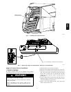
6. Slide the sampling tube collar over the sampling tube
until the tabs lock into the tube.
7. Slide sampling tube into smoke detector with eight slots.
Make sure sampling tube holes are aligned facing UP.
8. Insert plug into far end of the sampling tube.
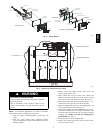
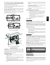
9. Place rubber gaskets over each sampling tube on smoke
detector. (See Fig. 2.)
10. Remove one knockout from top of smoke detector.
11. Insert one end of RJ-45 wire harness through knockout
and wire to smoke detector as shown in Fig. 10.
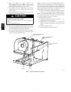
12. Slide smoke detector into holes in fan side plate with
the terminal block at the top and secure using two,
8-18
3
/
4
-in. pan head screws (P/N AL56AU168). Replace
cover.
EQUIPMENT DAMAGE HAZARD
Failure to follow this caution may result in equipment
damage.
Do not overtighten the screws.
CAUTION
!
13. Attach cable to fan side plate using snap- in wire ties.
See Fig. 9 for clarification. Secure to center po st.
14. Secure cable to back side of cable tray using three snap-in
wire ties.
15. In the Electrical/Compressor section, install snap bushing
in the center knockout underneath the terminal strips lo-
cated in the bottom right-hand corner of control box.
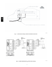
16. Connect wires to terminal strips as shown in Fig. 6 for
ComfortLinkt units or Fig. 7 for Electro--Mechanical
Units.
NOTE: This step is not needed with 48/50PG Humidi-- MiZert
units because they have plug 19 harness already in stalled in the
control box. The harness assembly part number 50TG403507
that came with the accessory is not used. Facto ry installed PL--19
can belocated outside the contol box by its appropriate label. For
Humidi--MiZer smoke detector wiring refer to Fig. 8.
17. Remove cover from control module and remove knockout
from side of module nearest the RJ-45 connector.
18. Using three 8-18
3
/
4
-in. pan head screws
(P/N AL56AU168) screws, secure control module to com-
pressor partition above compressor B1/A2 location.
19. Connect PL-19 from control module to PL-19 from wir-
ing harne ss installed in Step 16 .
NOTE: On 48PG Humidi-- MiZer units, the control box harness
has a jumper plug attached. This needs to be disconnected so
PL--19 from the smoke detector can be snapped in.
20. Route cable from supply smoke sensor, along the outside
of the control box, through the control module knockout
and connect to the J1 RJ-45 connector.
21. Using wire ties, secure the wiring so it does not interfere
with unit operation.
22. Replace control module cover.
23. Restore power to the unit.
24. Configure ComfortLink controller as specified in Config-
uring the ComfortLink Controller below.
25. Perform Sensor and Controller tests. At a minimum, the
Magnet test should be performed to verify smoke detector
wiring.
26. Turn off power to the unit.
27. Reconnect the indoor fan plug and the limit switch wires if
applicable.
28. Close the indoor fan section door.
29. Restore power to the unit and check for alarms. Correct
any problems encountered.
30. Close Electrical/Compressor section door.
Sensor In stallation (CRSMKSEN001A00)
When adding return smoke sensor to previously installed supply
smoke detector:
1. Open electrical/compressor section access door/panel.
2. Disconnect PL-19 from control module to terminal strip
by separating plug connectors.
3. Remove control module cover. Disconnect supply sensor
RJ-45 wire from control module.
4. Remove three screws attaching control module to com-
pressor partition and save screws for later use.
5. Remove control module from unit.
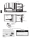
6. Slide feet of control module into receptacle on the return
sensor housing and secure from the backside using one
screw removed in Step 4. The J1 RJ-45 connector on sen-
sor should be nearest the control module. Knockout holes
should align. (See Fig. 11.)
7. Route short RJ-45 wire from J1 connector of sensor,
through knockout holes, and connect to J1 connector of
control module.
8. Fo llow steps 2-20 of instructions for installing return
smoke detector.
IMPORTANT: Step 15 requires connecting the supply smoke
sensor RJ--45 wire to connector J2 in the control module.
When adding supply smoke sensor to previously installed return
smoke detector:
Follow steps 1-14 and 19-29 from supply smoke detector
installation instructions.
CRSMK