


10
To perform a contro ller alarm test:
1. Press the controller’s test/reset switch for seven seconds.
Verify that the cont roller’ s Alarm LE D turns on.
2. After performing a controller alarm test, reset the sensor
by pressing the test/reset switch for two seconds. Verify
that the con troller’s Alarm LED turns off.
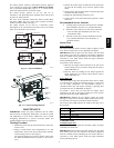
Controller Dirty T
est
The cont roller dirty test checks the controller’s ability to initiate a
sensor dirty test and indicate its results.
To pe rform a sensor dirty test, press the contro ller’s test/reset
switch for two seconds. Verify that the controller’s Trouble LED
flashes.
TROUBLESHOOTING
Dirty LED
Sensor’s Dirty LED is Flashing
Clean the sensor assembly as described in Cleaning Procedure.
Power LED
Sensor’s Power LED is OFF
1. Check the controller’s Power LED. If it is off, determine
why the controller does not have power and make the
necessary repairs.
2. Ch eck the wiring betw een the sensor and the controller . If
wiring is loose or missing, repair or replace as required.
Controller’s Power LED is
OFF
1. Make sure the circuit supplying power to the controller is
ope rational. If not, make sure JP2 and JP3 are set correctly
on the controller before applying power.
2. Verify that power is applied to the controller’ssupply in-
put terminals. If power is not present, replace or repair wir-
ing as required.
Trouble LED
Controller’s Trouble LED is On
1. Check the Trouble LED on each sensor connected to the
controller. If a sensor’s Trouble LED is on, determine the
cause and make the necessary repairs.
2. Ch eck the wiring between the sensor and the controller. If
wiring is loose or missing, repair or replace as required.
Controller’s Trouble LED is
Flashing
1. One or both of the sensors is 100%dirty. Determine which
sensor’s Dirty LED is flashing.
2. Clean the sensor assembly as de scribed in Cleaning
Procedure.
Sensor’s Trouble LED is
On
1. Check the sensor’s Dirty LED. If it is flashing, the sensor
is dirty and must be cleaned.
2. Check the sensor’s cover. If it is loose or missing, secure
the cover to the sensor housing.
3. Replace sensor assembly.
Sensor’s Trouble LED is On But Controller’s Trouble LED
is
Off
Remove JP1 on the controller.
Copyright2007 CarrierCorp.S 7310 W.MorrisSt.S Indianapolis, IN 46231
Manufacturer reserves the right tochange, atany time,specificationsand designs withoutnotice andwithout obligations.
Catalog No:48/50H,P---24SI
Replaces:48/50H,P---10SI
PrintedinU.S.A. EditionDate:7/07
CRSMK