


8
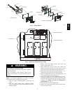
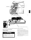
SMOKE DETECTOR
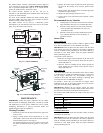
WIRE TIES
C07180
Fig. 9 --- Supply Smoke Detector Location and Wire Routing (Top View)
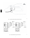
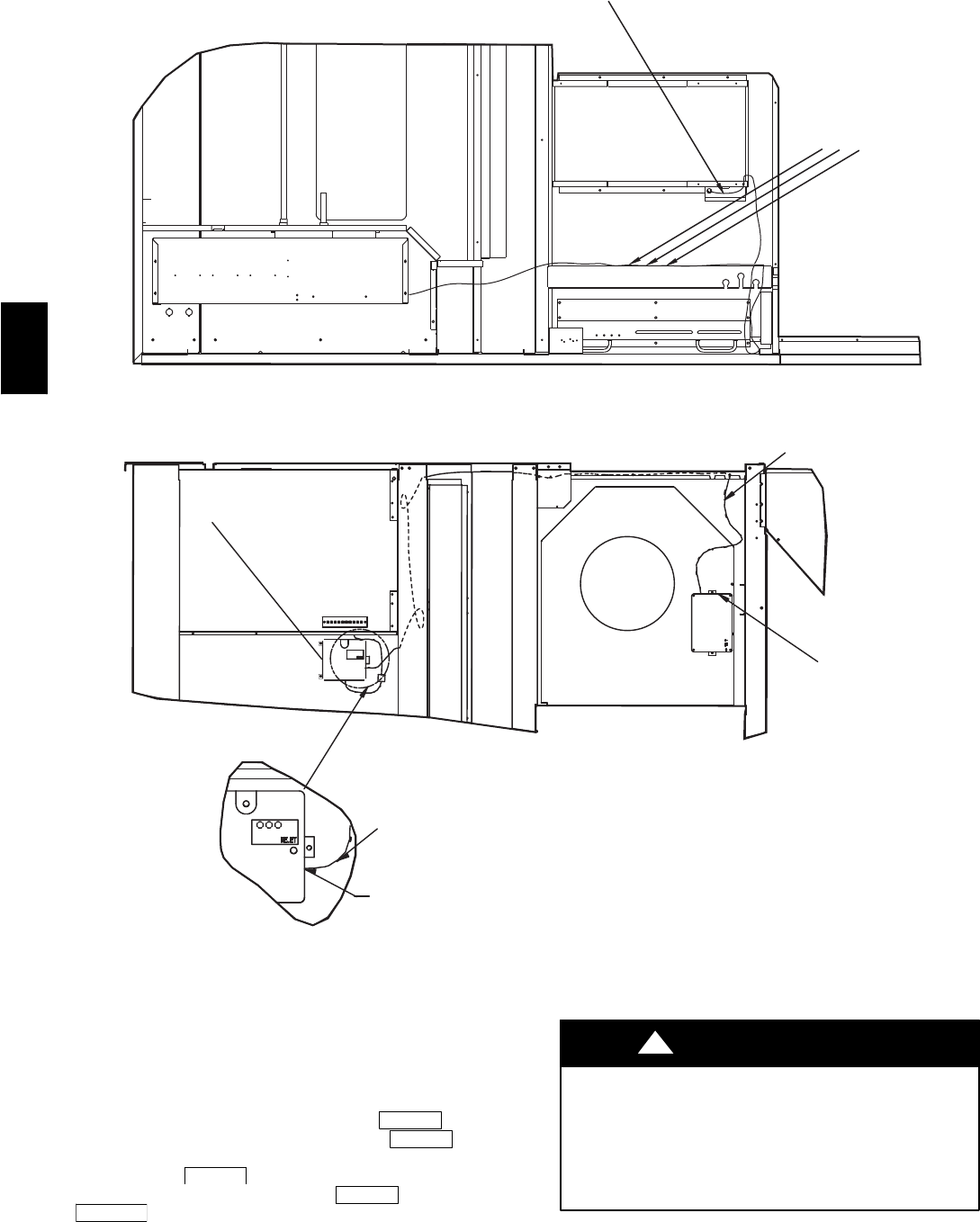
AS SHOWN TO
PLUG
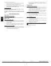
ROUTE RJ-45 HARNESS ALONG
SUPPLY SMOKE DETECTOR
THRU BOX, AND OUT
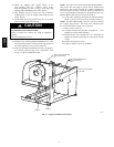
SMOKE POWER HARNESS
PUNCH OUT KNOCK OUT
INSTALL CONTROL
MODULE HERE
USING THREE SCREWS
RJ-45 HARNESS
CUT TAPE BEFORE
INSERTING SMOKE DETECTOR.
C07181
Fig. 10 --- Supply Control Module Installation (Side View)
Configuring the ComfortLinkt Controller
Configuration settings for the ComfortLink controller are
changed by using the Scrolling Marquee display. A password
may be required to edit the configurations, depending on the
previous settings configured in the unit. Default password is
“1111.” Use the arrow keys to scroll the red LED on the display
to the “Configur ation” position and press
ENTER
.Scroll
through the menu until UNIT is found and press
ENTER
.After
reaching the UNIT sub-menu , scroll to FS.SW (Fire Shut down
Input) and press
ENTER
twice, change the value to 1 (Norm al
Open) with the arrow keys, press
ENTER
again. Press
ESC APE
three times to return to the top level of the menu.
Additional information about changing configurations can be
found in the Control and Troubleshooting Guide for 48/50HG
and 48/50PG units.
OPERATION
EQUIPMENT DAMAGE HAZARD
Failure to follow this caution may result in damage to the
unit.
The smoke detector must be tested and maintained regularly
following NFPA 72 requirements. The smoke detector
should be cleaned at least once a year.
CAUTION
!
CRSMK