


6
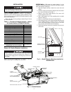
SMOKE RESPONSE TEST — Drill a
1
/
4
-in. hole 3 ft
upstream from the unit smoke detector. Use the Service Test
function (see Controls and Troubleshooting Guide for details
on Service Test) to turn on the unit indoor fan. Measure the air
velocity with an anemometer. Air speed must be at least
100 fpm. If the air speed is greater than 500 fpm, use a conven-
tional manometer to measure differential pressure between the
sampling tubes.
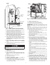
Spray aerosol smoke into the unit through the
1
/
4
-in. hole for
5 seconds. Wait two minutes for the unit smoke detector to
alarm. If the unit smoke detector alarms, then air is flowing
through the detector. Remove the unit smoke detector cover
and blow out the residual aerosol smoke from the chamber and
reset the unit smoke detector. Use duct tape to seal the aerosol
smoke entry hole.
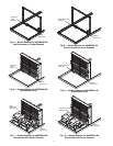
To determine if smoke is capable of entering the sensing
chamber, visually identify any obstructions. Plug the exhaust
and inlet tube holes to prevent unit air from carrying smoke
away from the detector head, then blow smoke directly at the
head to cause an alarm.
Standby, Alarm and Sensitivity Tests —
The cover
of the smoke detector must be removed to perform these tests.
STANDBY AND TROUBLE TEST
Standby — Look for presence of flashing green LED.
The LED should flash approximately every
10 seconds.
Trouble — If the detector LED does not flash, then the detec-
tor lacks power, the detector board is missing
(replace), the cover has been missing or not
secured properly for more than 20 minutes (secure
cover properly), or the unit is defective (return for
repair).
Test — The trouble condition can be caused intentionally
to verify correct operation of the system. Remove
the detector board to cause an alarm.
Cover
Tamper — If the cover is removed or not properly secured for
a period longer than 20 minutes, a trouble signal is
generated to indicate the cover is missing.
ALARM TEST
Magnet Test
1. Place the painted surface of the magnet onto the TEST
locator on the bottom of the housing.
2. The red alarm LED on the detector should switch on.
Verify system control panel alarm status and control
panel execution of all intended auxiliary functions
(i.e., fan shutdown, damper control, etc.).
3. The detector must be reset by the front cover reset button.
SENSITIVITY TEST — After verification of alarm capability,
use a field-supplied voltmeter to check detector sensitivity. The
housing cover must be removed to perform this test. If readings
indicate that the detector head is outside of the acceptable range
that is printed on the label of the detector, the detector chamber
requires cleaning.
Remove the plugs after this test, or the smoke detector will
not function properly and damage may result.