


3
8. Insert tube end plug into sampling tube and slide sam-
pling tube into bottom hole of smoke detector.
9. Remove the unit side panel at the return end of the unit
(downshot units only). Save screws for use later.
10. Mount the sampling tube support bracket to the cross
member with two
1
/
4
AB-14
5
/
8
-in. screws as shown in
Fig. 4. Insert snap bushing into hole in bracket.
11. Slide sampling tube into bracket, making sure that the
sampling holes point in the opposite direction of the re-
turn air flow. Insert the sampling tube all the way into the
smoke detector.
12. Return to the auxiliary control box and secure sampling
tube to smoke detector with two no. 6 self-tapping
screws.
13. Attach smoke detector to partition using two, 8-18
3
/
4
-in.
pan head screws. See Fig. 4.
14. Return to side panel and insert tube end plug into
sampling tube.
15. Replace the unit side panel.
16. Return to auxiliary control box section and insert sam-
pling tube filters into both sampling tube holders. (See
Fig. 1.)
17. Connect harness PL13 as shown in Fig. 3.
18. Restore power to the unit.
19. Configure ComfortLink™ controller as specified in
Controls and Troubleshooting Guide.
20. Perform Standby, Alarm, and Sensitivity Tests on page 6.
At a minimum, the Magnet test should be performed to
verify smoke detector wiring.
21. Replace smoke detector cover.
22. Check for alarms. Correct any problems.
23. Close and secure auxiliary control box door.
48/50Z Units —
The return air smoke detector is to be
installed on the upright in the power exhaust section. See
Fig. 5-10.
NOTE: For size 075-105 units with return fan option, the
smoke detector should be installed in the return duct. Do not
use the bracket provided in this accessory kit.
1. Open the power exhaust section doors/panels on both
sides of the unit to gain access.
2. Find plug 13 in the power exhaust section.
3. Remove cover from smoke detector. The screws will re-
main captured in the cover.
4. Place foam gaskets over each sampling tube on smoke
detector. See Fig. 1.
5. Remove one knockout from top of smoke detector.
6. Insert stripped ends of wire harness through knockout and
wire to smoke detector as shown in Fig. 3. Use ground
screw in the smoke detector to secure a wire tie. Use wire
tie to provide strain relief for the wire harness.
7. Mount the smoke detector bracket 50ZZ500420 on the
upright.
See Fig. 5 for size 030-050 units without economizer.
See Fig. 6 for size 030-050 units with economizer only
option.
See Fig. 7 for size 030-050 units with economizer and
power exhaust option.
See Fig. 8 for size 055-105 units without economizer.
See Fig. 9 for size 055-105 units with economizer only
option.
See Fig. 10 for size 055-105 units with economizer and
power exhaust option.
8. Slide smoke detector into holes in bracket. Do not secure
at this time.
9. Insert tube end plug into sampling tube and slide
sampling tube into bottom hole of smoke detector.
10. Mount the sampling tube bracket to the bottom of the
power exhaust section using two
1
/
4
AB-14-
5
/
8
-in. screws.
For size 030-050 units with power exhaust, use bracket
50ZZ500431 as shown on Fig. 7. For all other units
use bracket 50ZZ500421, as shown on Fig. 5 and 6 for
size 030-050 units, Fig. 8-10 for size 055-105 units.
Do not overtighten the screws. Damage to smoke detector
may result.
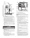
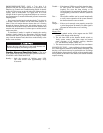
GROUND
SCREW
SMOKE
DETECTOR
PL13
SAMPLING
TUBE
FILTERS
WIRE HARNESS
Fig. 3 — Smoke Detector Wiring Connections
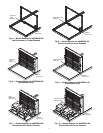
SMOKE
DETECTOR
WIRE
HARNESS
SAMPLING
TUBE
SUPPORT
BRACKET
SAMPLING
TUBE
Fig. 4 — Smoke Detector Installed (48/50A020-060)