


5
11. Slide sampling tube into bracket, making sure the
sampling holes point in the opposite direction of the
return airflow. Insert the sampling tube all the way into
the smoke detector.
12. Secure sampling tube to smoke detector with two no. 6
self-tapping screws.
13. Attach smoke detector to the bracket using two 8-18
3
/
4
-in. pan head screws.
14. Insert the tube end plug into sampling tube.
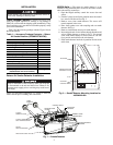
15. Insert sampling tube filters into both sampling tube hold-
ers. See Fig. 1.
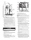
16. Connect harness PL13 as shown on Fig. 3.
17. Restore power to the unit.
18. Configure ComfortLink™ controller as specified in
Controls and Troubleshooting Guide.
19. Perform Standby, Alarm, and Sensitivity Tests. At a
minimum, the Magnet test should be performed to verify
smoke detector wiring.
20. Replace smoke detector cover.
21. Check for alarms. Correct any problems.
22. Close and secure all doors and panels.
Configuring the
Comfort
Link Controller —
For
configuration settings refer to the Control and Troubleshooting
Guide for 48/50A020-060 and 48/50Z030-105 units.
OPERATION
The smoke detector accessories contain a photoelectric
detector approved for an extended air speed range of 100 to
4000 feet per minute (0.5 to 20.3 m/s) and an operational
temperature range of 32 to 131 F (0° to 55 C). Do not operate
the smoke detector outside of these ranges.
The smoke detector operates on 24 VAC, 120 VAC, or
240 VAC. The thermostat power terminals on the unit are used
to power the smoke detector. Alarm and supervisory relay con-
tacts are available for control panel interface (alarm initiation),
HVAC control, and other auxiliary functions. Auxiliary relays
are also provided for fan shut down or signaling of up to 9
other detectors in the loop for multiple fan shut down. The
smoke detector is not designed for 2-wire applications.
The smoke detector can be reset by a momentary power
interruption, by the reset button on the front cover, by the
control panel, or by the remote reset accessory. The smoke
detector incorporates a cover tamper feature that provides
a trouble signal after 20 minutes if the cover is removed or
improperly installed. Proper installation of the cover removes
the trouble condition.
MAINTENANCE
Cleaning Procedure —
Notify the proper authorities
that the smoke detector system is undergoing maintenance, and
that the system will temporarily be out of service. Disable the
zone or system undergoing maintenance to prevent unwanted
alarms and possible dispatch of the fire department.
AIR FILTERS
1. Turn off power to the system.
2. Remove and inspect sampling tube filters.
3. If filters are heavily coated with dirt, replace them with
new filters. If they are not heavily coated, use a vacuum
cleaner or compressed air nozzle to remove dust, then
reinstall the filters.
PHOTO DETECTOR BOARD
1. Remove the screen by gently grasping on each side and
pulling straight off.
2. Lift the photo chamber in the same fashion. Vacuum the
screen and cover. Use clean, compressed air to loosen and
blow out any remaining debris.
3. Vacuum photo chamber, then use clean compressed air to
blow area clean.
4. Replace the chamber by pressing it onto the base. Press
the screen into place. It should fit tightly on the chamber.
Filter Replacement —
The filters do not substantially
affect smoke detector performance even when up to 90% of the
filter is clogged. Quarterly visual inspection usually suffices to
determine whether the filters should be replaced. Only a high
percentage of contamination affects performance. If further
testing is required, compare differential pressure readings with
and without the filters installed. If the difference exceeds 10%,
then replace the filters. The pressure differential should never
fall below 0.0015 in. wg.
Board Replacement
SMOKE DETECTOR BOARD REPLACEMENT
1. Remove the two detector board mounting screws.
2. Pull gently on the board to remove it.
3. To replace the board, align the board mounting features,
holes, and the interconnect terminals. Push the board into
place.
4. Secure board with the two mounting screws.
POWER BOARD REPLACEMENT
1. Disconnect wiring from the terminal block.
2. Remove the two power board mounting screws.
3. Pull gently on the board to remove it.
4. To replace the board, align the board mounting features,
holes, and the interconnect terminals. Push the board into
place.
5. Secure board with the two mounting screws.
6. Re-connect wiring to terminal block.
TROUBLESHOOTING
Test and maintain unit smoke detectors as recommended in
NFPA 72. Before conducting these tests, notify the proper
authorities that the smoke detection system will be temporarily
out of service. Disable the system under test to prevent unwanted
alarms.
Smoke Entry Tests
AIRFLOW TEST — The smoke detector is designed to
operate over an extended air speed range of 100 to 4000 fpm.
To verify sufficient sampling of unit air, turn on the unit
indoor fan using the Service Test function (see Controls and
Troubleshooting Guide for details on Service Test) and use a
manometer to measure the differential pressure between the
two sampling tubes.
The differential pressure should measure at least 0.0015 in. wg
and no more than 1.2 in. wg. Because most commercially avail-
able manometers cannot accurately measure very low pressure
differentials, applications with less than 500 fpm of unit air speed
may require the use of a current-sensing pressure transmitter or
the use of aerosol smoke (see Smoke Response Test on page 6).
The smoke detector must be tested and maintained regu-
larly following NFPA 72 requirements. The smoke detector
should be cleaned at least once a year. Damage to equip-
ment may result.