


42VMC
GB - 6
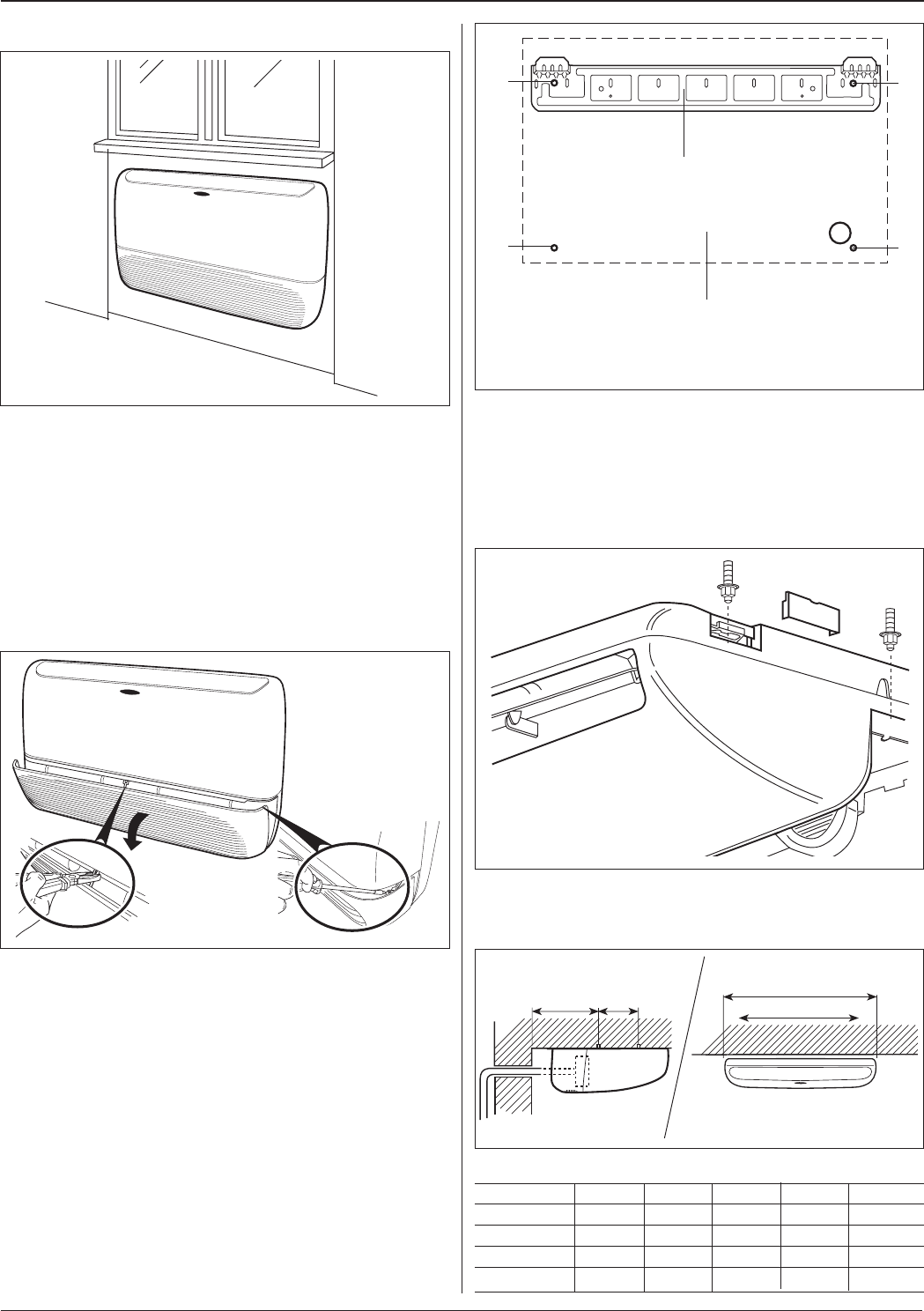
Installation
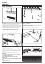
D
C
B
A
ᕡ
ᕡ
ᕡ
ᕡ
ᕢ
ᕣ
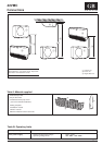
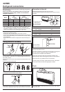
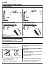
ᕡ Hole
ᕢ Plate
ᕣ Template
Vertical wall-mounting
• The preferred arrangement is generally under a window sill on an
external wall.
This makes it easier to install the interconnecting tubing,
electrical connections and condensate pipework to the outdoor
unit.
The indoor unit can also be installed against an internal partition
if the connections to the outdoor unit can be concealed.
• For better operation of the thermostat located on the unit, it is
advisable to avoid unit installation in enclosed spaces.
• There are three alternatives for the connections to the unit:
parallel to the wall, through the wall or through the side.
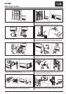
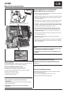
Preparation
• Unpack the unit.
• Open and remove the suction grille.
To remove suction grille, remove the central lock using a pliers,
then with a screwdriver remove the two side screws fixing the
fasteners.
• Locate the mounting template, supplied with the unit.
Installation
• Use the template supplied, and drill the four fixing holes in the
wall. Use the four dowels provided.
• Fix the attachment plate (using the two upper holes).
• Attach the unit.
• Fix the unit to the wall, using the two holes, positioned in the lower
part.
• Verify that the unit is level.
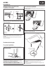
Ceiling installation
• Using the template supplied, drill the four holes in the ceiling and
position four tie rods (not supplied).
• Attach the unit to the tie-rods, as shown in the illustration.
• Ensure a minimum slope of 5 mm (refrigerant connection side
must be lower) by modifying on the tie-rod fixing.
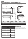
42VMC 009 012 014 018 024
A mm 850 850 1000 1000 1000
B mm 786 786 940 940 940
C mm 237 237 250 250 250
D mm 237 237 285 285 285