


ELECTRIC HEAT
Application —
Electric heaters are available for
in-stallation on Carrier fan coil units in the following
applications.
TOTAL ELECTRIC HEAT — This system provides com-
plete heating during the heating season; no boiler is re-
quired. Heating and cooling are now available on an indi-
vidual basis throughout the year with a 2-pipe system.
Chilled water is used for cooling and the electric heater is
used for heating. Room controls can be supplied for
either manual or automatic changeover.
AUXILIARY ELECTRIC HEAT — This system is used for
heating between seasons or during the cooling season when
chilled water is being circulated. Individual room controls
are supplied to provide electric heat only when chilled water
is being circulated through the system. Water flow through
the unit is shut off when the heater is turned on.
During the winter heating season, heating is provided
by hot water circulated through the system. A changeover
device locks out the electric heat when the hot water is
circulated.
Heater Construction
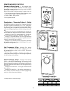
STRIP HEATERS — Used with Model 42C ceiling units,
Model 42D ducted units and Model 42S stack units.
These heaters consist of coils of the highest grade
resistance wire, insulated by ceramic insulators in alumi-
nized brackets.
All heaters except those used in 42S stack units are po-
sitioned on the incoming (preheat) side of the unit coil. On
42S stack units, the strip heater is located in the fan dis-
charge on the leaving side of the coil.
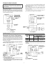
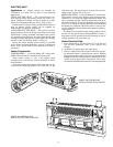
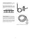
SHEATH HEATERS — Used with Model 42V vertical units.
These heaters consist of the highest grade resistance wire,
centered in a
1
⁄
2
-in. diameter copper-plated steel sheath. The
wire is insulated from the sheath by magnesium oxide pow-
der packed around it. To increase the heater surface exposed
to air, a 1
1
⁄
4
-in. OD fin of copper-plated steel is wound around
the sheath in a continuous spiral that makes 5 turns per lin-
eal inch. Sheath and fin are permanently bonded together by
copper brazing.
The heaters are positioned on the leaving (reheat) side of
the unit coil. On special units with high efficiency motors, a
strip heater will be installed in the fan discharge on the in-
coming (preheat) side of the unit coil.
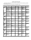
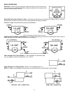
Heater Electrical Data
1. Load voltage may be 120, 208, 240 or 277 volts. For unit
size and kW limitations, refer to the specific unit
catalogs.
2. All heaters are single stage and single phase.
3. Unless a single power-source option is selected, the elec-
tric heat units require 2 separate power sources. With the
single power-source option, only one line circuit need be
brought into the unit. Fuse protection is added to the motor/
control circuit to protect these components. This is sepa-
rate from the field-furnished total unit overcurrent protection.
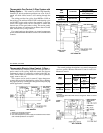
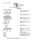
MODEL 42V VERTICAL UNIT
WITH ELECTRIC SHEATH HEATER
MODEL 42C CEILING UNIT
WITH ELECTRIC STRIP HEATER
9