


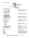
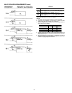
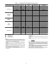
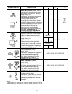

Table 1 — Acceptable Field-Furnished Pneumatic Valves
MANUFACTURER VALVE NUMBER TYPE MODE
SIZE (in.)
(OD Male Flare)
CAPACITY
(CV) RATING
HONEYWELL
VP517A 3-WAY MIXING
7
⁄
8
3.0, 4.0, 6.3
VP522A&B 3-WAY SEQUENCING
5
⁄
8
or
7
⁄
8
1.6/2.5 or 2.5/3.5/4.0
VP526A 3-WAY MIXING
5
⁄
8
1.6, 2.5
VP527A 2-WAY N.O.
1
⁄
2
0.63, 1.0, 1.6
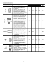
VP513A 2-WAY N.O.
5
⁄
8
or
7
⁄
8
2.5, 4.0
VP513B 2-WAY N.C.
5
⁄
8
1.0, 1.6, 2.5
VP531A 2-WAY N.O.
5
⁄
8
or
7
⁄
8
(ODS) 1.6, 2.6, 3.3
JOHNSON
SERVICE
V4332 3-WAY MIXING
1
⁄
2
1.2, 2.0
V4334 3-WAY MIXING
5
⁄
8
4.7
V4440 3-WAY SEQUENCING
1
⁄
2
1.4, 2.4
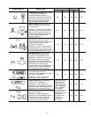
V4440 3-WAY SEQUENCING
5
⁄
8
4.1, 4.7
V3766 2-WAY N.O.
1
⁄
2
1.0, 1.7, 3.2
V3966 2-WAY N.C.
1
⁄
2
1.7, 3.2
BARBER-
COLEMAN
VK9312 3-WAY MIXING
5
⁄
8
2.0, 4.0
VK9332 3-WAY SEQUENCING
5
⁄
8
1.7, 2.4, 4.0
VK9212 2-WAY N.O.
5
⁄
8
0.4, 1.3, 2.2, 3.3
VK9222 2-WAY N.C.
5
⁄
8
0.4, 1.3, 2.2, 3.3
MCC
POWERS
VP656-0011, 10, 09 3-WAY MIXING
1
⁄
2
1.5, 2.5
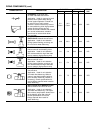
VP658-0004, 5 3-WAY DIVERTING
1
⁄
2
2.5
VP658-0050, 51 3-WAY SEQUENCING
1
⁄
2
1.5, 2.5
VP658-0004, 5 2-WAY N.O.
1
⁄
2
1.0, 2.5
VP656-0002, 4 2-WAY N.O.
1
⁄
2
0.9, 2.1
VP656-0012 2-WAY N.C.
1
⁄
2
2.1
ROBERTSHAW
2582 (V8200) 2-WAY N.O.
1
⁄
2
0.4, 0.6, 1.0, 1.6
2583 (V8300) 3-WAY MIXING
1
⁄
2
1.6
2561 (V6101) 2-WAY N.C.
1
⁄
2
,
5
⁄
8
1.2, 2.2, 4.1
2561 (V6102) 2-WAY N.O.
1
⁄
2
1.0, 1.6
2563 (V6300) 3-WAY MIXING
1
⁄
2
1.6
2563 (V6301) 3-WAY MIXING
5
⁄
8
2.5
2569 (V6900, 01) 3-WAY SEQUENCING
1
⁄
2
,
5
⁄
8
,
7
⁄
8
.6, 1.0, 1.1, 1.6,
2.5, 3.2, 2.4, 4.0, 4.5
C
V
— See Note 5.
N.C. — Normally Closed
N.O. — Normally Open
OD — Outside Diameter
NOTES:
1. This reference table lists valves that are acceptable because of
capacity and pipingconnection type.Actual valve selection forspe-
cific mode (N.O. or N.C.) and capacity rating (C
V
) to meet jobsite
conditions must be made by field personnel.
2. Valve size (
1
⁄
2
-,
5
⁄
8
-, and
7
⁄
8
-in. OD) designates the matching tub-
ing size.
Use price page package 18-2 or 18-4 for selecting
1
⁄
2
-in. or
5
⁄
8
-in.
OD valves. Use price page package 18-3 or 18-5 for
7
⁄
8
-in. OD
valves.
3. The
1
⁄
2
-in. and
5
⁄
8
-in. OD valves are used primarily on 42C(ceiling)
and 42V (vertical) room fan coil units. The
7
⁄
8
-in. OD valves are
recommended for use on 42D (ducted) units.
4. Flare connections are 45° SAE flare with body threaded for stand-
ard flare nuts.
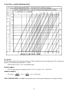
5. The C
V
capacity rating is the gpm flow through a valve at 1.0 psi
pressure drop.
EXAMPLE: A 2.5 C
V
valve has a flow of 2.5 gpm at 1.0 psi pres-
sure drop.
As flow changes, pressure drop can be determined by the
formula:
Actual gpm
2
P=
C
V
6. Restrictions imposed by limited pipingenclosures often require that
the valve manufacturer’s recommendationfor obstruction free serv-
ice clearances be waived. Service/isolation valvesnormally speci-
fied will permit removal of the entirepneumatic valve for field serv-
ice if necessary.
7. Certaincombinations of piping accessoriesand control valves have
proven unacceptable in the past, therefore the factory must re-
serve the right of review for final acceptance.
8. Consult factory on all applications involving valves with thermo-
static actuators or built in pneumatic thermostats.
23