


19
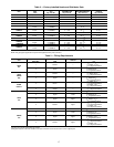
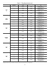
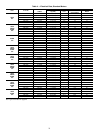
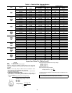
Table 3 — Fitting Requirements (cont)
*See Fig. 6 for access hole location by number.
†Fittings are listed in order from header or tee stub connection out to access hole in corner support post.
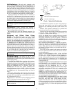
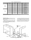
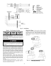
Chilled Water Piping — See Tables 1C and 1F for
chilled water connection sizes. For ease in brazing, it is recom-
mended that all internal solder joints be made before unit is
placed in final position.
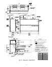
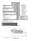
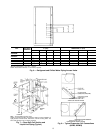
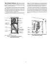
Knockouts are provided in the unit corner posts for 40RM
and 40RMQ refrigerant piping; additional field-fabricated ac-
cess holes are required for 40RMS chilled water piping. See
Fig. 6, which lists recommended knockouts and access holes to
use for each 40RMS unit size.
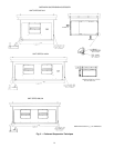
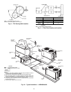
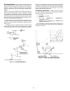
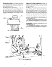
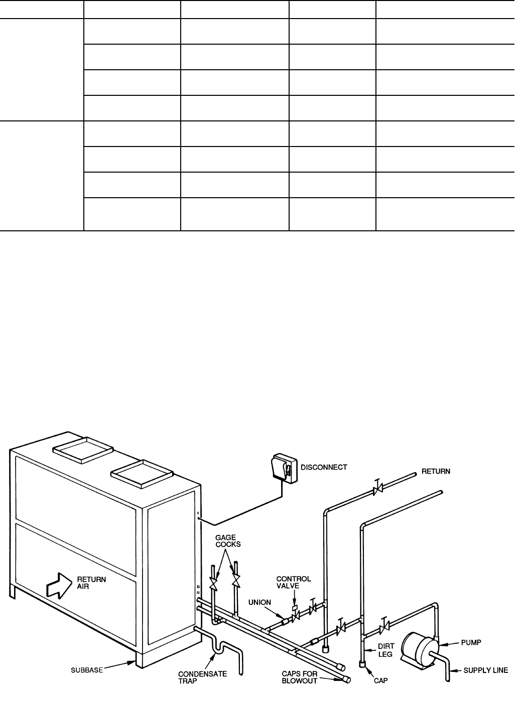
To size, design, and install chilled water piping, consult the
Carrier System Design manual. See Fig. 12 for an example of a
typical installation. Recommended fittings are listed in Table 3.
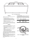
To access 40RMS coil vents and drains, remove the unit
side panel over the coil header. Vent and drain plugs are on the
top and bottom of header, respectively. See the Service section
for information on preventing coil freeze-up during winter.
UNIT
ACCESS
HOLE NO.*
CONNECTION
TYPE
CIRCUIT
FITTINGS REQUIRED†
(in.)
40RMS
028, 034
5 Supply Lower
2
1
/
8
Long Radius Elbow
2
1
/
8
Nipple, 3
1
/
2
L
2
1
/
8
Long Radius Elbow
6 Return Lower
2
1
/
8
Long Radius Elbow
2
1
/
8
Nipple, 3 L
2
1
/
8
Long Radius Elbow
7 Return Upper
2
1
/
8
Long Radius Elbow
2
1
/
8
Nipple, 6
7
/
8
L
2
1
/
8
Long Radius Elbow
8 Supply Upper
2
1
/
8
Long Radius Elbow
2
1
/
8
Nipple, 11
7
/
8
L
2
1
/
8
Long Radius Elbow
40RM
034
1 Suction Lower
1
3
/
8
Street Elbow
1
3
/
8
Nipple, 3 L
1
3
/
8
Long Radius Elbow
2 Liquid Lower
5
/
8
Street Elbow
5
/
8
Nipple, 7
3
/
4
L
5
/
8
Long Radius Elbow
3 Liquid Upper
5
/
8
Street Elbow
5
/
8
Nipple, 18
1
/
2
L
5
/
8
Long Radius Elbow
4 Suction Upper
1
3
/
8
Nipple, 4
3
/
16
L
1
3
/
8
Long Radius Elbow
1
3
/
8
Nipple, 19
1
/
4
L
1
3
/
8
Long Radius Elbow
Fig. 12 — Typical 40RMS Chilled Water Piping