


16
RETURN
AIR
SUBBASE
ACCESSORY
15 DIAMS
MIN
40RMQ024
UNIT
ELECTRIC
HEATER
ACCESSORY
24 V
CONTROL
WIRE
BULB CAPILLARY
TUBES
10 DIAMS
MIN
CONDENSATE
DRAIN
8 DIAMS
MIN
DISCONNECT
PER NEC
INSULATED
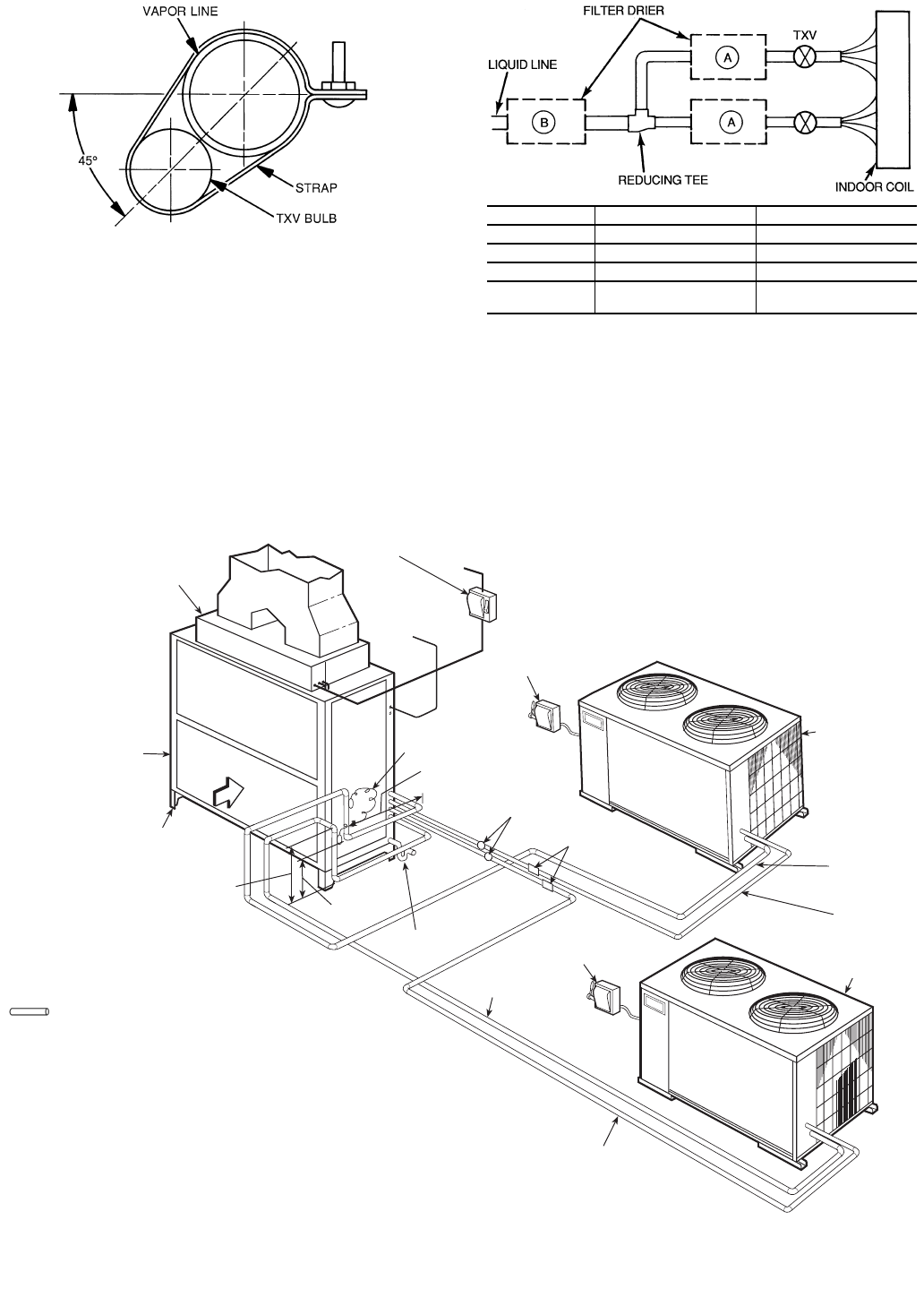
VAPOR LINE
FUSED
DISCONNECT
SWITCH*
FUSED
DISCONNECT
SWITCH*
SIGHT
GLASS*
FILTER
DRIER*
INSULATED
VAPOR LINE
LIQUID
LINE
CONDENSING
UNIT A
CONDENSING
UNIT B
LIQUID
LINE
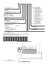
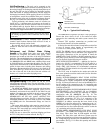
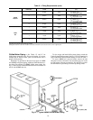
LEGEND
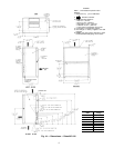
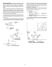
TXV — Thermostatic Expansion Valve
NOTE: The 8 o’clock position is shown above.
Fig. 9 — TXV Sensing Bulb Location
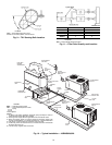
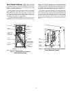
LEGEND
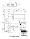
*Field supplied.
NOTES:
1. All piping must follow standard refrigerant piping techniques. Refer to
Carrier System Design Manual for details.
2. All wiring must comply with the applicable local and national codes.
3. Wiring and piping shown are general points-of-connection guides only
and are not intended for, or to include all details for, a specific installation.
4. Filter driers must be bi-flow type suited for heat pump duty.
5. Condensing unit A should be the first on and last off and be connected to
the lower half of the coil.
6. Internal factory-supplied TXVs not shown.
NEC — National Electrical Code
TXV — Thermostatic Expansion Valve
Piping
Fig. 10 — Typical Installation — 40RMQ024,028
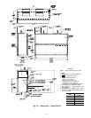
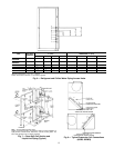
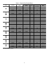
LEGEND
TXV — Thermostatic Expansion Valve
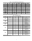
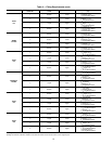
Fig. 11 — Filter Drier Quantity and Location
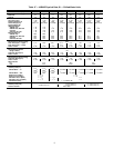
UNIT QUANTITY REQUIRED FIGURE REFERENCE
38ARQ008,012 1B
38AQS016 2A
38ARQ012 (2) 2A
38ARQ012,
AQS016
2A