


8
INSTALLATION
Mixing Box
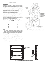
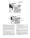
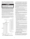
DAMPER ACTUATORS — The 39L mixing boxes are sup-
plied with low leak dampers and blade and edge seals. Damper
operating torques are shown in Table 2.
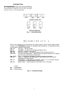
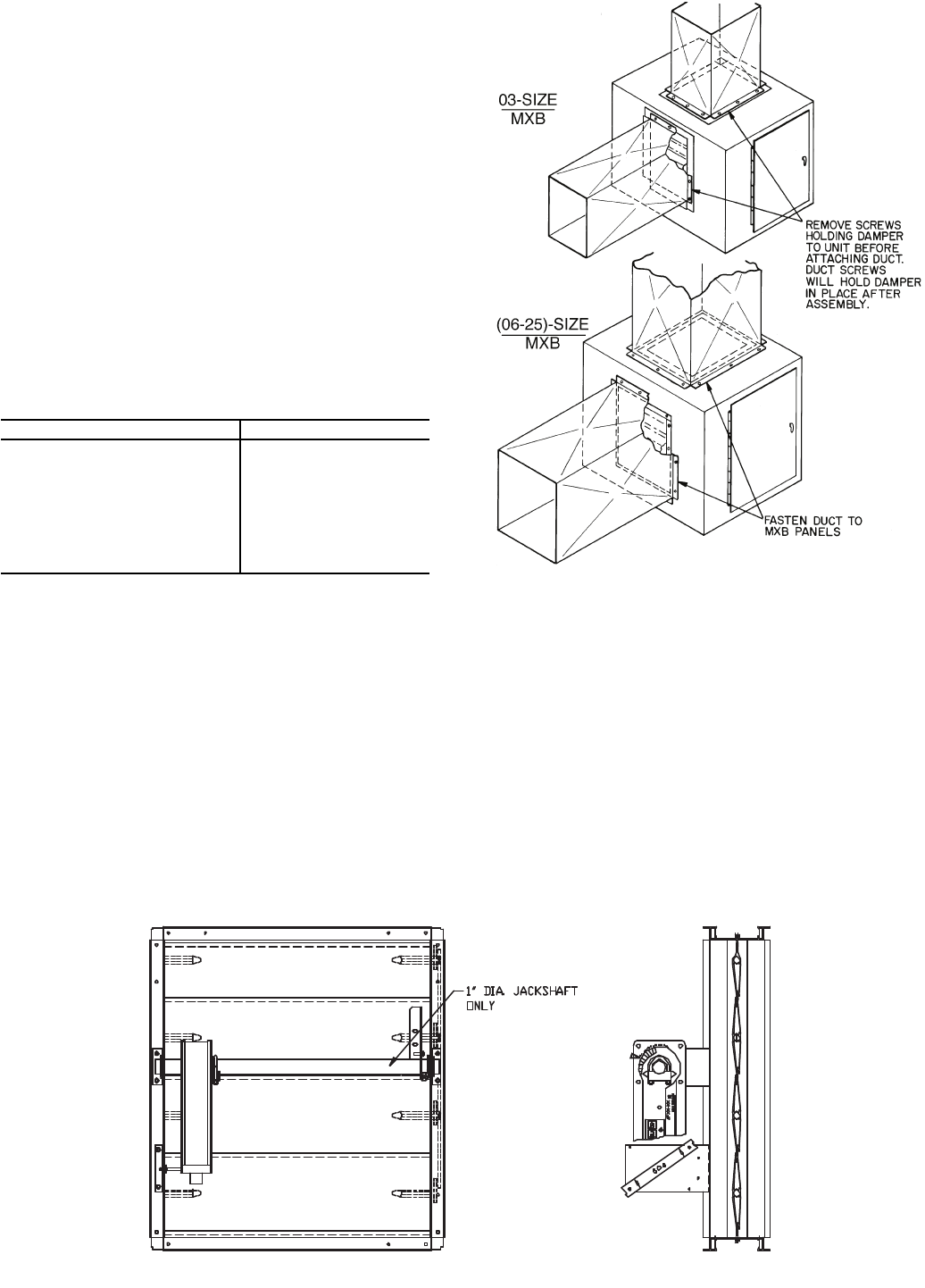
The actuator and mounting brackets are field supplied and
may be mounted inside or outside the unit. A typical inside
mounting bracket is shown in Fig. 8. For external mounting of
actuators, drill or punch a hole in the exterior panel.
NOTE: If the unit is shipped with AirManager™ controls,
actuator(s) are factory-supplied. Refer to Table. 3.
To ensure torque is transmitted equally to both damper sec-
tions, actuator must be connected to the 1-in. hollow jackshaft
that drives the interconnecting linkage bar. Connection to any
other shaft is not recommended.
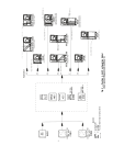
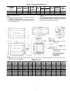
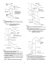
DUCTWORK ATTACHMENT — Ductwork should be
flanged out and attached to the mixing box panels as shown in
Fig. 9. See Fig. 10 for duct connection sizes.
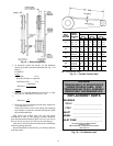
Table 2 — Mixing Box Damper Operating Torque
(in.-lb)
NOTES:
1. Torque values are based on interconnected dampers driven by
one operator. For units with separate operators for each
damper, calculate torque as follows: Table values x .80 = torque
per damper section.
2. Damper shaft moves 90 degrees from open to closed position.
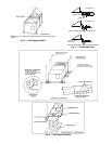
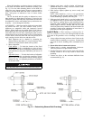
Condensate Drain — Install a trapped condensate drain
line at unit drain connection. Use 1-in. standard pipe.
Measure maximum design negative static pressure up-
stream from the fan. Referring to Fig. 7, height “H” must be
equal to or larger than negative static pressure at design operat-
ing conditions. Prime enough water in trap to prevent losing
seal (Differential 1). When the fan starts, Differential 2 is equal
to the maximum negative static pressure.
Provide freeze-up protection as required.
39L UNIT SIZE TORQUE
03 20
06 20
08 26
10 29
12 33
15 41
18 52
21 56
25 76
MXB — Mixing Box
Fig. 9 — Mixing Box Ductwork Attachment
Fig. 8 — Typical Mixing Box Actuator Mounting