


15
When a water coil is applied downstream of a direct-
expansion (DX) coil, a freeze-up thermostat must be installed
between the DX and water coil and electrically interlocked to
turn off the cooling to prevent freeze-up of the water coil.
For outdoor-air application where intermittent chilled water
coil operation is possible, one of the following steps should be
taken:
• Install an auxiliary blower heater in cabinet to maintain
above-freezing temperature around coil while unit is
shut down.
• Drain coils and fill with an ethylene glycol solution suit-
able for the expected cold weather operation. Shut down
the system and drain coils. See Service section, Winter
Shutdown, page 30.
STEAM COILS — When used for preheating outdoor air in
pressure or vacuum systems, an immersion thermostat to con-
trol outdoor-air damper and fan motor is recommended. This
control is actuated when steam supply fails or condensate tem-
perature drops below an established level, such as 120 to 150 F.
A vacuum breaker should also be used to equalize coil pressure
with the atmosphere when steam supply throttles close. Steam
should not be modulated when outdoor air is below 40 F.
On low-pressure and vacuum steam-heating systems, the
thermostat may be replaced by a condensate drain with a ther-
mal element. This element opens and drains the coil when con-
densate temperature drops below 165 F. Note that condensate
drains are limited to 5 psig pressure.
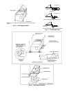
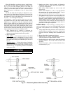
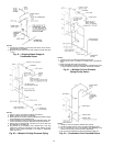
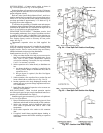
INNER DISTRIBUTING TUBE STEAM COILS — The
inner distributing tube (IDT) steam coil used in the Carrier
39M air-handling units has an inner tube pierced to facilitate
the distribution of the steam along the tube's length. The outer
tubes are expanded into plate fins. The completed assembly
includes the supply and condensate header and side casings
which are built to slant the fin/tube bundle back toward the
condensate header. The slanting of the assembly ensures that
condensate will flow toward the drains. This condensate must
be removed through the return piping to prevent premature
failure of the coil. The fin/tube bundle is slanted vertically for
horizontal airflow coils, and horizontally for vertical air-
flow coils.
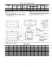
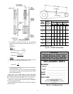
IDT Steam Coil Piping
— The following piping guidelines
will contribute to efficient coil operation and long coil life:
1. Use full size coil outlets and return piping to the steam
trap. Do not bush return outlet to the coil. Run full size to
the trap, reduce at the trap.
2. Use float and thermostatic (F & T) traps only for conden-
sate removal. Trap size selection should be based on the
difference in pressure between the steam supply main and
the condensate return main. It is good practice to select a
trap with 3 times the condensate rating of the coil to
which it is connected.
3. Use thermostatic traps for venting only.
4. Use only
1
/
2
-in., 15-degree swing check valves installed
horizontally, piped open to atmosphere, and located at
least 12 in. above the condensate outlet. Do not use
45-degree, vertical lift and ring check valves.
5. The supply valve must be sized for the maximum antici-
pated steam load.
6. Do not drip steam mains into coil sections. Drip them on
the pressure side of the control valve and trap them into
the return main beyond the trap for the coil.
7. Do not use a single trap for two or more coils installed in
series. Where two or more coils are installed in a single
bank, in parallel, the use of a single trap is permissible,
but only if the load on each coil is equal. Where loads in
the same coil bank vary, best practice is to use a separate
trap for each coil.
Variation in load on different coils in the same bank may
be caused by several factors. Two of the most common
are uneven airflow distribution across the coil and stratifi-
cation of inlet air across the coil.
8. Do not try to lift condensate above the coil return into an
overhead main, or drain into a main under pressure with a
modulating or on/off steam control valves. A pump
and receiver should be installed between the coil conden-
sate traps and overhead mains and return mains under
pressure.
9. Use a strainer (
3
/
32
-in. mesh) on the steam supply side,
as shown in the piping diagrams, to avoid collection of
scale or other foreign matter in the inner tube distributing
orifices.
NOTE: IDT coils must be installed with the tubes draining
toward the header end of the coil. Carrier's IDT steam coils
are pitched toward the header end as installed in the unit.
10. Ensure the AHU (air-handling unit) is installed level to
maintain the inherent slope. Also ensure the unit is in-
stalled high enough to allow the piping to be installed cor-
rectly, especially the traps which require long drip legs.
11. Do not fail to provide all coils with the proper air vents to
eliminate noncondensable gasses.
12. Do not support steam piping from the coil units. Both
mains and coil sections should be supported separately.
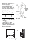
IDT Steam Coil Installation
— Refer to drawings to position
the coils properly with regard to the location of the supply and
return connections. Ensure that the IDT coil is pitched with the
tubes draining toward the header. Carrier’s AHUs provide
proper coil pitch when the AHU is installed level.
Refer to schematic piping diagrams and piping connection
notes for the recommended piping methods.
NOTES:
1. Flange or union is located to facilitate coil removal.
2. Flash trap may be used if pressure differential between steam
and condensate return exceeds 5 psi.
3. When a bypass with control is required.
4. Dirt leg may be replaced with a strainer. If so, tee on drop can
be replaced by a reducing ell.
5. The petcock is not necessary with a bucket trap or any trap
which has provision for passing air. The great majority of high
or medium pressure returns end in hot wells or deaerators
which vent the air.
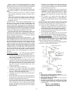
Fig. 18 — Low, Medium or
High Pressure Coil Piping