


36
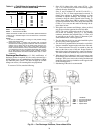
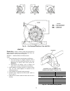
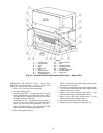
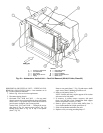
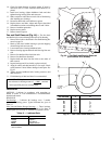
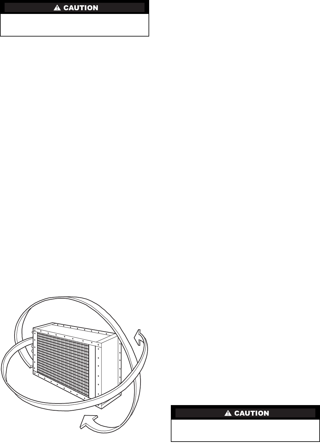
STEAM INNER DISTRIBUTING TUBE COILS — Rotate
in horizontal plane and reinstall. See Fig. 42.
PIPING — Direct expansion, chilled water, and hot water
coils should always be piped for counterflow. (Fluid should
enter the coil at the leaving-air side.) Steam coils must have the
condensate connection at bottom of coil.
To determine intervals for cleaning coils in contaminated air
operations, pressure taps should be installed across the coils
and checked periodically. Abnormal air pressure drop will indi-
cate a need for cleaning the coils.
Annual maintenance should include:
1. Clean the line strainers.
2. Blow down the dirt leg.
3. Clean and check operation of steam traps.
4. Check operation of control valves.
5. Check the operation of check valves to prevent conden-
sate flowback.
6. Check operation of thermostatic air vents, if used. A float
and thermostatic trap will contain a thermostatic air vent.
When the bellows is ruptured, it will fail closed.
7. Check operation of vacuum breakers.
8. Check operation of the thermal protection devices used
for freeze-up protection.
9. Steam or condensate should not be allowed to remain in
the coil during the off season.This will prevent the forma-
tion and build up of acids.
There are additional precautions and control strategies, as
found in various catalogues and in the ASHRAE Fundamentals
Handbook and in the Carrier System Design Guide — Piping
Section, when the entering-air temperature to the coil falls be-
low 35 F. These conditions occur when IDT coils are used for
pre-heat and/or face and bypass applications.
Freeze up protection:
1. Use a strainer in the supply line and the dirt leg ahead of
the trap.
2. Use a vacuum breaker in the return.
3. Do not use overhead returns from the coil. A floodback
can occur.
4. An immersion thermostat to control outdoor-air dampers
and the fan motor is recommended. This control is acti-
vated when the steam supply fails or the condensate
temperature drops below a predetermined temperature,
usually 120 F.
5. On low pressure and vacuum systems, the immersion
thermostat may be replaced by a condensate drain with a
thermal element. This element opens and drains the coil
when the condensate temperature drops below 165 F.
Note the thermal condensate drain is limited to 5 psig
pressure. At greater coil pressures they will not open.
In spite of the precautions listed above, a coil may still
freeze up. An oversize capacity coil, at partial load, with a
modulating steam control valve will occasionally freeze.
Freezing occurs in the 20 F to 35 F range of entering-air
temperatures. A better installation would be an undersize coil,
with an on/off control valve with thermostatic control in the
outside air, set at 35 F air temperature, installed downstream of
the first coil; or setting the minimum steam pressure at 5 psig.
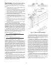
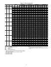
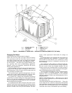
Filters
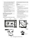
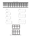
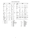
FILTER SECTIONS — See Table 12 for filter data. Filters
are field supplied.
On the size 03 angle filter, a spacer is required on each side
of the filters.
Flat filter section can use 2-in. or 4-in. thick filters. (Size 03
accepts 2-in. filters only.) The flat filter section as shipped ac-
cepts 2-in. filters. Remove angle spacer in each filter track to
provide the 4-in. space required to accommodate 4-in. filters.
On all filter sections except size 03, filters are pushed into
the track until they touch the opposite side of the unit. Any re-
maining space is taken up by the adjustable 2-piece sheet metal
spacer. See Fig. 43 for filter arrangements.
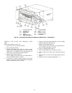
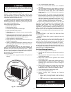
Fan Shaft Bearing Removal
1. Lock open and tag electrical disconnect.
2. Enter through fan section access door or remove panels as
required.
3. Place plywood or other rigid covering on floor to protect
insulation from damage.
4. Block wheel so that it will not pinwheel due to natural
draft through the unit.
5. Loosen motor base to frame bolts. Adjust motor to re-
lease belt tension so removal of belts is done without
stretching. Do not stretch belts over sheaves. Damage to
belt can result.
6. Remove bolts on bushing of fan shaft sheave, insert bolts
in jacking hole provided on bushing and slowly jack
bushing from sheave. Then remove bushing on sheave.
7. Loosen bearing setscrews and locking collar.
8. Remove bearing holddown bolts.
9. Remove bearing while observing the following
precautions:
a. Make certain fan shaft surface is not rough or
scored. If so, clean up surface with fine emery
cloth.
b. Add a few drops of oil after cleanup of shaft end.
Chilled and hot water coils must not be rotated horizon-
tally. If coils are rotated horizontally, severe water blow-off
will result.
It should not be necessary to drive a new bearing onto
shaft. If light tapping is needed, do not tap against outer
race.
DX AND ALL
WATER COILS
STEAM COILS
ONLY
Fig. 42 — Coil Rotation