


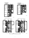
SEQUENCE OF OPERATION — With power supplied to indoor
and outdoor units, transformer is energized.
Cooling
On a call for cooling, the thermostat makes circuits R-O, R-Y, and
R-G. Circuit R-O energizes the reversing valve, switching it to
cooling position. Circuit R-Y energizes contactor, starting outdoor
fan motor and compressor circuit. R-G energizes indoor unit
blower relay, starting indoor blower motor on high speed.
When thermostat is satisfied, its contacts open, de-energizing
contactor and blower relay. Compressor and motors should stop.
Heating
On a call for heating, the thermostat makes circuits R-Y and R-G.
Circuit R-Y energizes contactor, starting outdoor fan motor and
compressor. Circuit R-G energizes indoor blower relay, starting
blower motor on high speed.
Should the temperature continue to fall, R-W2 is made through
second-stage room thermostat bulb. Circuit R-W2 energizes a
sequencer, bringing on first bank of supplemental electric heat and
providing electrical potential to second heater sequencer (if used).
If outdoor temperature falls below the setting of outdoor thermo-
stat, (field-installed option) contacts close to complete circuit and
bring on second bank of supplemental electric heat.
When thermostat is satisfied, its contacts open, de-energizing
contactor and sequencer. All heaters and motors should stop.
Defrost
The defrost control is a time/temperature control which includes a
field-selectable (quick connects located at board edge) time period
between defrost cycles (30, 50, and 90 minutes), factory set at 90
minutes.
The electronic timer and defrost cycle will start only when
contactor is energized and defrost thermostat is closed.
The defrost mode is identical to cooling mode except that the
outdoor fan motor stops and second-stage heat is turned on to
continue warming conditioned space.
To initiate defrost, the defrost thermostat must be closed. This can
be accomplished as follows:
1. Turn off power to outdoor unit.
2. Disconnect outdoor fan motor lead from OF2 on control
board. Tape lead to prevent grounding.
3. Restart unit in heating mode, allowing frost to accumulate on
outdoor coil.
4. After a few minutes in heating mode, liquid-line temperature
should drop below the closing point of defrost thermostat,
approximately 30˚F.
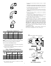
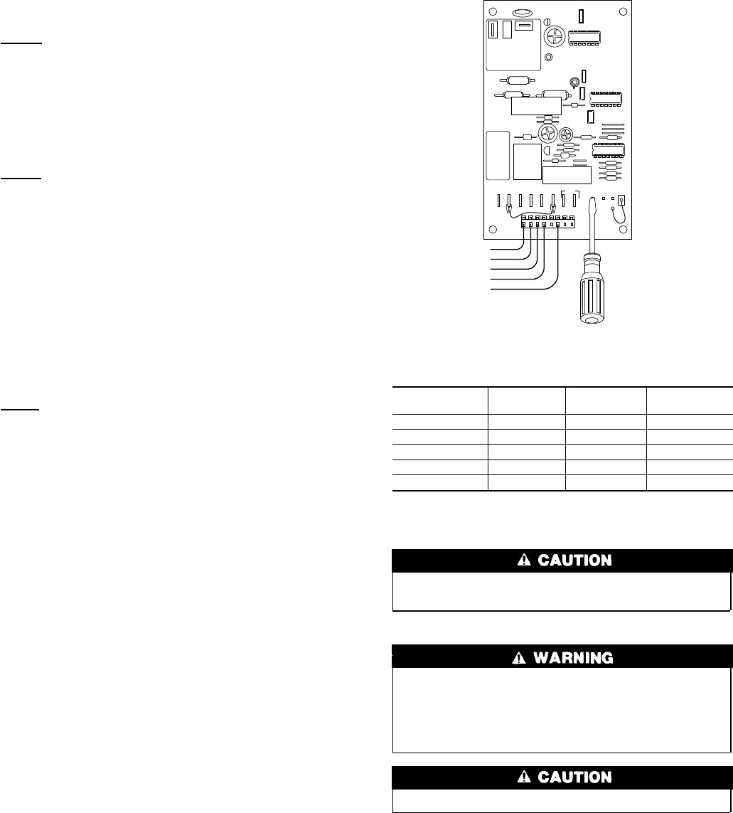
5. Short between speed-up terminals with a flat bladed screw-
driver. (See Fig. 11.) This reduces the timing sequence to
1/256 of the original time.
6. When you hear reversing valve change position, remove
screwdriver immediately. Otherwise the control will terminate
normal 10-minute defrost cycle in approximately 2 sec.
NOTE: Length of defrost cycle will be dependent upon the length
of time it takes to remove screwdriver from test pins after
reversing valve has shifted.
7. Unit will remain in defrost for remainder of defrost cycle time
or until defrost thermostat reopens.
Step 10—Checking Charge
Do not vent refrigerant to atmosphere. Recover during system
repair or final unit disposal.
Factory charge is shown on unit rating plate. (See Fig. 2.)
Service valve gage ports are not equipped with Schrader
valves. To prevent personal injury, make sure gage manifold
is connected to the valve gage ports before moving valves off
fully back seated position. Wear safety glasses and gloves
when handling refrigerant.
Compressor damage may occur if system is overcharged.
Check charge in cooling and heating mode by following procedure
shown on subcooling charging tables located on unit information
plate.
CARE AND MAINTENANCE
For continuing high performance, and to minimize possible
equipment failure, it is essential that periodic maintenance be
performed on this equipment. Consult User’s Manual for proper
frequency of maintenance. Frequency of maintenance may vary
depending upon geographic areas, such as coastal applications.
Step 1—Leave User’s Manual with Homeowner
Explain system operation and maintenance procedures outlined in
User’s Manual.
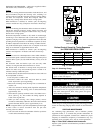
Fig. 11—Defrost Control
Defrost Control Speed-Up Timing Sequence
for CES0110063/CES0130024
PARAMETER MINIMUM MAXIMUM
SPEED-UP
(NOMINAL)
30-min cycle 27 33 7 sec
50-min cycle 45 55 12 sec
90-min cycle 81 99 21 sec
10-min cycle 9 11 2 sec
5-min cycle 4.5 5.5 1 sec
A91444
OF1
OF2
O
R
T2 Y
TI
DFT
C
TEST
30
50 90
W1
O
R
W2
Y
C
CES0110063,
CES0130024
6