


NOTE: In some cases noise in the living area has been traced to
gas pulsations from improper installation of equipment.
INSTALLATION RECOMMENDATIONS
1. Locate unit away from windows, or areas where unit operating
sounds may disturb customer.
2. Ensure that vapor and liquid tube diameters are appropriate to
capacity of unit. (See Table 1.)
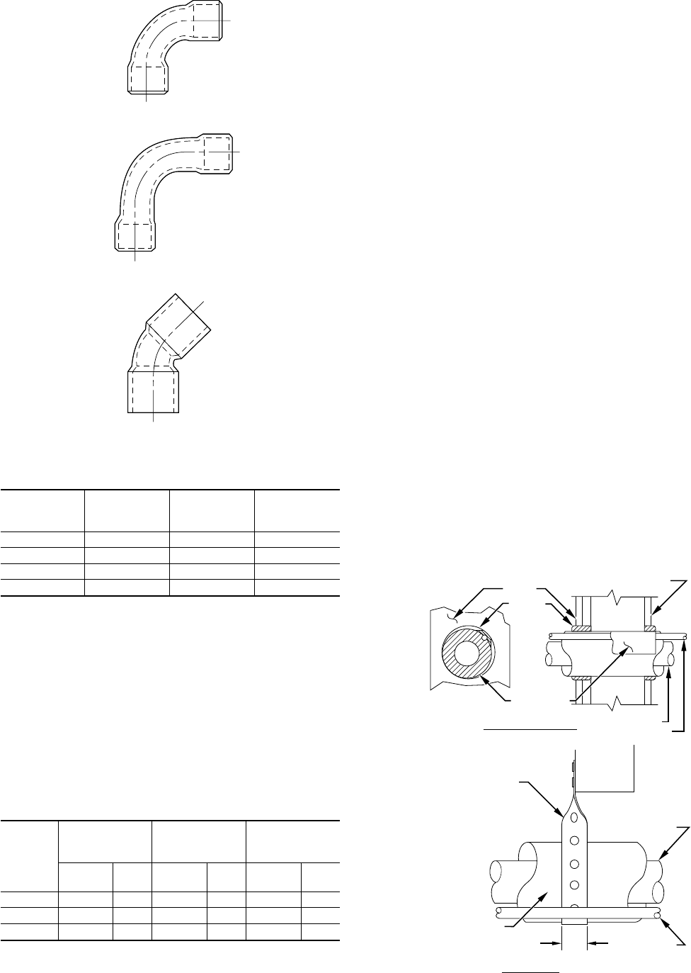
3. Run refrigerant tubes as directly as possible by avoiding
unnecessary turns and bends.
4. Leave some slack between structure and unit to absorb
vibration.
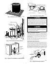
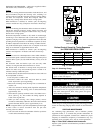
5. When passing refrigerant tubes through wall, seal opening
with RTV or other pliable silicon-based caulk. (See Fig. 9.)
6. Avoid direct lineset contact with water pipes, ductwork, floor
joists, wall studs, floors, and walls.
7. Do not suspend refrigerant tubing from joists and studs with a
rigid wire or strap which comes in direct contact with tubing.
(See Fig. 9.)
8. Ensure that tubing insulation is pliable and it completely
surrounds vapor tube.
9. When necessary, use hanger straps which are 1 in. wide and
conform to shape of tubing insulation. (See Fig. 9.)
10. Isolate hanger straps from insulation by using metal sleeves
bent to conform to shape of insulation.
If refrigerant tubes or indoor coil is exposed to atmospheric
conditions for longer than 5 minutes, it must be evacuated to 500
microns to eliminate contamination and moisture in the system.
OUTDOOR UNITS CONNECTED TO FACTORY-APPROVED
INDOOR UNITS — Outdoor unit contains correct system refrig-
erant charge for operation with indoor approved unit when
connected by 15 ft of field-supplied or factory accessory tubing.
Check refrigerant charge for maximum efficiency. (See Step
10—Checking Charge.)
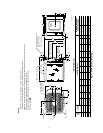
REFRIGERANT TUBING — Connect tubing to fittings on out-
door unit vapor- and liquid-service valves. (See Fig. 2.)
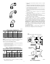
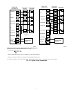
Fig. 8—Tube Bend Losses for Long Lines
Fitting Losses in Equivalent Ft
TUBE
SIZE
OD (IN.)
90˚ STD
FIG. 8-A
90˚ L.R.
FIG. 8-B
45˚ STD
FIG. 8-C
5/8 1.6 1.0 0.8
3/4 1.8 1.2 0.9
7/8 2.0 1.4 1.0
1-1/8 2.6 1.7 1.3
A92498
90° LONG RAD
B
90° STD
A
45° STD
C
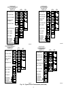
→ Table 1—Refrigerant Connections and
Recommended Liquid- and Vapor-Tube Diameters
UNIT
SIZE
LIQUID (IN.) VAPOR (IN.)
VAPOR
(LONG LINE)
(IN.)
Connect
Dia
Tube
Dia
Connect
Dia
Tube
Dia
Connect
Dia
Tube
Dia
024 3/8 3/8 5/8 5/8 5/8 3/4
030, 036 3/8 3/8 3/4 3/4 3/4 7/8
042, 048 3/8 3/8 7/8 7/8 7/8 7/8
Note: Tube diameters are for lengths up to 50 ft. For tubing lengths greater
than 50 ft, consult Long-Line Application Guideline.
Fig. 9—Piping Installation
A92469
OUTDOOR
WALL
CAULK
INDOOR WALL
NOTE:
AVOID CONTACT BETWEEN TUBING AND STRUCTURE
VAPOR TUBE
LIQUID TUBE
LIQUID TUBE
THROUGH THE WALL
JOIST
HANGER STRAP
(AROUND VAPOR
TUBE ONLY)
VAPOR TUBE
INSULATION
INSULATION
1
″
MIN
SUSPENSION
4