


DO NOT BURY MORE THAN 36 IN. OF REFRIGERANT
TUBING IN GROUND. If any section of tubing is buried,
there must be a 6-in. vertical rise to the valve connections on
the outdoor unit. If more than the recommended length is
buried, refrigerant may migrate to cooler buried section
during extended periods of unit shutdown, causing refrigerant
slugging and possible compressor damage at start-up.
Due to system design, this unit must be installed with a
factory-listed indoor section. Non-approved coils could cause
performance and reliability problems. Refer to pre-sale litera-
ture for approved indoor sections.
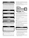
Step 5—Check Defrost Thermostat
Check defrost thermostat to ensure it is properly located and
securely attached. There is a liquid header with a brass distributor
and feeder tube going into the outdoor coil. At the end of 1 of the
feeder tubes there is a 3/8-in. OD stub tube approximately 3-in.
long. (See Fig. 7.)
The defrost thermostat should be located on the stub tube. Note
that there is only 1 stub tube used with the liquid header and on
most units it will be the bottom circuit.
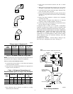
Step 6—Make Piping Connections
Outdoor units may be connected to indoor sections using service
parts tubing package or field-supplied refrigerant grade tubing of
correct size and condition. For tubing requirements beyond 50 ft,
substantial capacity and performance losses can occur. Following
the Long-Line Application Guideline, which is available from your
local distributor, will reduce these losses and improve system
reliability. Refer to Fig. 8 for field tubing equivalent line length.
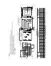
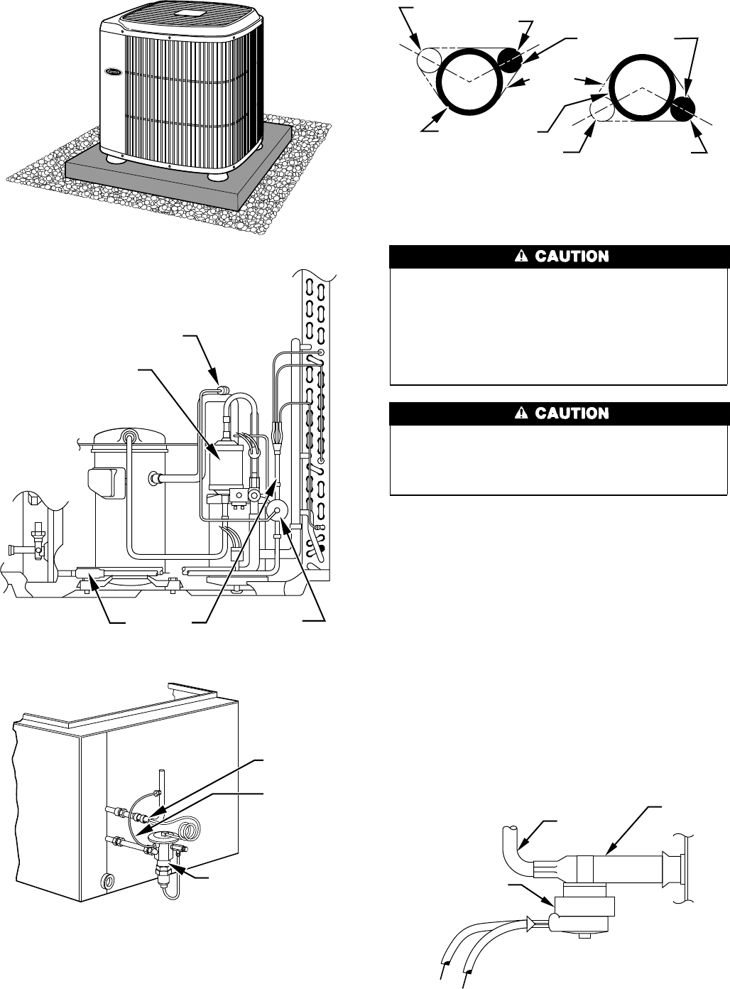
Fig. 3—Accessory Heat Pump Feet
A96419
Fig. 4—TXV Location on Outdoor Section
A96433
TXVTXV
STRAINER
SENSING BULB
DISCHARGE
MUFFLER
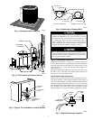
Fig. 5—Typical TXV Installation on Indoor Section
A88382
THERMOSTATIC
EXPANSION
VALVE
EQUALIZER
TUBE
SENSING
BULB
COIL
Fig. 6—Positioning of Sensing Bulb
A81032
2 O'CLOCK
10 O'CLOCK
SENSING BULB
STRAP
SUCTION TUBE
8 O'CLOCK
4 O'CLOCK
7
⁄
8
IN. OD & SMALLER
LARGER THAN
7
⁄
8
IN. OD
DEFROST
THERMOSTAT
FEEDER
TUBE
STUB
TUBE
A96527
Fig. 7—Defrost Thermostat Location
3