


38YSA
Heat Pump—Outdoor Section
Installation and Start-Up Instructions
NOTE: Read the entire instruction manual before starting the
installation.
This symbol → indicates a change since the last issue.
SAFETY CONSIDERATION
Improper installation, adjustment, alteration, service, maintenance,
or use can cause explosion, fire, electrical shock, or other
conditions which may cause personal injury or property damage.
Consult a qualified installer, service agency, or your distributor or
branch for information or assistance. The qualified installer or
agency must use factory-authorized kits or accessories when
modifying this product. Refer to the individual instructions pack-
aged with the kits or accessories when installing.
Follow all safety codes. Wear safety glasses and work gloves. Use
quenching cloth for brazing operations. Have fire extinguisher
available. Read these instructions thoroughly and follow all
warnings or cautions attached to the unit. Consult local building
codes and the National Electrical Code (NEC) for special instal-
lation requirements.
Recognize safety information. This is the safety-alert symbol
.
When you see this symbol on the unit or in instructions and
manuals, be alert to the potential for personal injury.
Understand the signal words DANGER, WARNING, and CAU-
TION. These words are used with the safety-alert symbol. DAN-
GER identifies the most serious hazards which will result in severe
personal injury or death. WARNING signifies hazards which
could result in personal injury or death. CAUTION is used to
identify unsafe practices which would result in minor personal
injury or product and property damage.
Before installing or servicing system, always turn off main
power to system. There may be more than 1 disconnect
switch. Turn off accessory heater power if applicable. Elec-
trical shock can cause personal injury or death.
INSTALLATION
Step 1—Check Equipment and Jobsite
UNPACK UNIT — Move to final location. Remove carton, taking
care not to damage unit.
INSPECT EQUIPMENT — File claim with shipping company,
prior to installation, if shipment is damaged or incomplete. Locate
unit rating plate on unit corner panel.
It contains information needed to properly install unit. Check
rating plate to be sure unit matches job specifications.
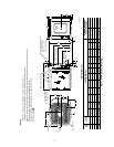
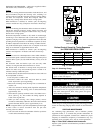
Step 2—Install on a Solid, Level Mounting Pad
If conditions or local codes require unit be attached to pad,
tie-down bolts should be used and fastened through knockouts
provided in unit base pan. Refer to unit mounting pattern in Fig. 2
to determine base pan size and knockout hole location.
When installing, allow sufficient space for airflow clearance,
wiring, refrigerant piping, and service. Allow 30-in. clearance to
service end of unit and 48 in. above unit. For proper airflow, a 6-in.
clearance on 1 side of unit and 12 in. on all remaining sides must
be maintained. Maintain a distance of 24 in. between units.
Position so snow or ice from roof or eaves cannot fall directly on
unit.
On rooftop applications, locate unit at least 6 in. above roof
surface. Place unit above a load-bearing wall and isolate unit and
tubing set from structure. Roof-mounted units exposed to winds
above 5 mph may require wind baffles to achieve adequate defrost.
Consult low-ambient guideline for wind baffle construction.
Arrange supporting members to adequately support unit and
minimize transmission of vibration to building. Consult local
codes governing rooftop applications.
NOTE: Unit must be level to within ±2˚ per compressor manu-
facturer specifications.
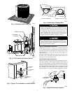
Step 3—Elevate Unit
For proper drainage, heat pump must be raised off of mounting
surface. Fig. 3 shows unit with accessory heat pump feet installed.
Use accessory heat pump snow rack in areas where prolonged
subfreezing temperatures or heavy snow occur. Refer to separate
Installation Instructions packaged with accessories.
For proper unit operation and reliability, this unit must be
installed with hard shutoff TXV on indoor section. Do not
install with evaporator coils having capillary tube or piston-
type metering devices.
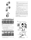
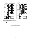
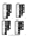
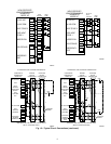
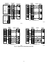
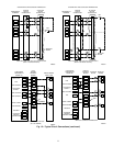
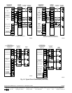
Step 4—Thermostatic Expansion Valve
The outdoor section is factory equipped with a hard shutoff TXV
for metering refrigerant during heating mode. See Fig. 4-6
for location of TXV and sensing bulb in system.
Fig. 1—Model 38YSA
A92446
Visit www.carrier.com
Manufacturer reserves the right to discontinue, or change at any time, specifications or designs without notice and without incurring obligations.
Book 1 4
Tab 5a 5a
PC 101 Catalog No. 563-811 Printed in U.S.A. Form 38YSA-2SI Pg 1 4-97 Replaces: 38YSA-1SI