


5. Set room thermostat at HEAT or COOL and fan switch at ON
or AUTO, as desired. Operate unit for 15 minutes. Check
system refrigerant charge. (See Step 10.)
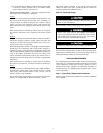
SEQUENCE OF OPERATION — With power supplied to indoor
and outdoor units, transformer is energized.
Cooling
On a call for cooling, the thermostat makes circuits R-O, R-Y, and
R-G. Circuit R-O energizes the reversing valve, switching it to
cooling position. Circuit R-Y energizes the contactor, starting
outdoor fan motor and compressor circuit. R-G energizes the
indoor unit blower relay, starting the indoor blower motor on high
speed.
When the thermostat is satisfied, its contacts open, de-energizing
the contactor and blower relay. Compressor and motors should
stop.
Heating
On a call for heating, the thermostat makes circuits R-Y and R-G.
Circuit R-Y energizes contactor, starting outdoor fan motor and
compressor. Circuit R-G energizes the indoor blower relay, start-
ing the blower motor on high speed.
Should the temperature continue to fall, R-W2 is made through the
second-stage room thermostat bulb. Circuit R-W2 energizes a
sequencer, bringing on the first bank of supplemental electric heat
and providing electrical potential to the second heater sequencer (if
used). If the outdoor temperature falls below the setting of the
outdoor thermostat (field-installed option), the contacts close to
complete the circuit and bring on the second bank of supplemental
electric heat.
When the thermostat is satisfied, its contacts open, de-energizing
the contactor and sequencer. All heaters and motors should stop.
Defrost
The defrost control is a time/temperature control which includes a
field-selectable (quick connect pins located at edge of circuit
board) time period between defrost cycles (30, 50, and 90
minutes), factory set at 90 minutes.
The electronic timer and the defrost cycle will start only when the
contactor is energized and the defrost thermostat is closed.
The defrost mode is identical to the cooling mode except the
outdoor fan motor stops and a second-stage heat is turned on to
continue warming the conditioned space.
Step 10—Checking Charge
Do not vent refrigerant to atmosphere. Recover during system
repair or final unit disposal.
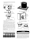
Factory charge is shown on unit rating plate. (See Fig. 2.)
Service valve gage ports are not equipped with Schrader
valves. To prevent personal injury, make sure valves are fully
back seated before removing gage port caps. Wear safety
glasses and gloves when handling refrigerant.
Compressor damage may occur if system is overcharged.
Adjust charge in cooling mode by following procedure shown on
the subcooling charging tables located on unit information plate.
Check charge in heating mode by following procedure shown on
heating check chart located on unit information plate.
CARE AND MAINTENANCE
For continuing high performance and to minimize possible equip-
ment failure, it is essential that periodic maintenance be performed
on this equipment. Consult your servicing contractor or User’s
Manual for the proper frequency of maintenance. Frequency of
maintenance may vary depending upon geographic areas, such as
coastal applications.
Step 1—Leave User’s Manual with Homeowner
Explain system operation and maintenance procedures outlined in
User’s Manual.
5