


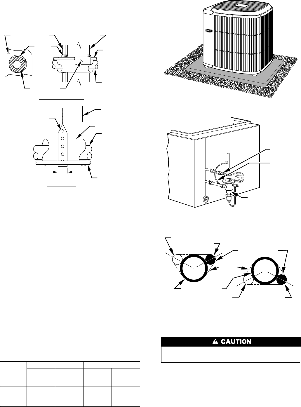
7. Do not suspend refrigerant tubing from joists and studs with a
rigid wire or strap which comes in direct contact with the
tubing. (See Fig. 3.)
8. Ensure that tubing insulation is pliable and completely sur-
rounds the vapor tube.
9. When necessary, use hanger straps which are 1 in. wide and
conform to the shape of the tubing insulation. (See Fig. 3.)
10. Isolate the hanger straps from the insulation by using metal
sleeves bent to conform to the shape of the insulation.
If refrigerant tubes or indoor coil is exposed to atmospheric
conditions for longer than 5 minutes, it must be evacuated to 500
microns to eliminate contamination and moisture in the system.
OUTDOOR UNITS CONNECTED TO FACTORY-APPROVED
INDOOR UNITS — Outdoor unit contains correct system refrig-
erant charge for operation with indoor unit of the same size when
connected by 15 ft of field-supplied or factory accessory tubing.
Check refrigerant charge for maximum efficiency. (See Step
10—Checking Charge.)
REFRIGERANT TUBING — Connect refrigerant tubing to fit-
tings on outdoor unit vapor and liquid service valves. (See Fig. 2.)
Table 1—Refrigerant Connections and Recom-
mended Liquid and Vapor Tube Diameters (In.)
UNIT
SIZE
LIQUID VAPOR
Connect
Diameter
Tube
Diameter
Connect
Diameter
Tube
Diameter
→ 018 3/8 3/8 5/8 5/8
024-030 3/8 3/8 3/4 3/4
036-048 3/8 3/8 7/8 7/8
060 3/8 3/8 7/8 1-1/8
Note: Tube diameters are for lengths up to 50 ft. For tubing lengths greater
than 50 ft, consult Long-Line Application Guideline.
To avoid valve damage while brazing, service valves must be
wrapped with a heat sinking material such as a wet cloth.
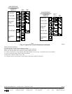
SWEAT CONNECTION — Use refrigerant grade tubing. Service
valves are closed from factory and ready for brazing. After
wrapping the service valve with a wet cloth, the tubing set can be
brazed to the service valve using either silver bearing or non-silver
bearing brazing material. Remove plastic retainer holding outdoor
piston in the liquid service valve and connect sweat adapter
provided to valve. (See Fig. 7.) Consult local code requirements.
Refrigerant tubing and indoor coil are now ready for leak testing.
This check should include all field and factory joints.
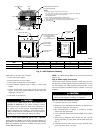
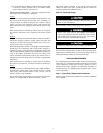
→ Fig. 3—Piping Installation
A94028
INSULATION
VAPOR TUBE
LIQUID TUBE
OUTDOOR WALL INDOOR WALL
LIQUID TUBE
VAPOR TUBE
INSULATION
CAULK
Avoid contact between tubing and structureNOTE:
THROUGH THE WALL
HANGER STRAP
(AROUND VAPOR
TUBE ONLY)
JOIST
1″ MIN.
SUSPENSION
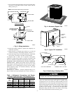
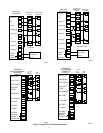
Fig. 4—Accessory Support Feet
A93567
Fig. 5—Typical TXV Installation
A88382
THERMOSTATIC
EXPANSION
VALVE
EQUALIZER
TUBE
SENSING
BULB
COIL
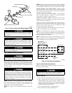
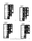
Fig. 6—Positioning of Sensing Bulb
A81032
2 O'CLOCK
10 O'CLOCK
SENSING BULB
STRAP
SUCTION TUBE
8 O'CLOCK
4 O'CLOCK
7
⁄
8
IN. OD & SMALLER
LARGER THAN
7
⁄
8
IN. OD
3