


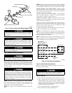
Install TXV kit to indoor coil as follows:
1. Install suction tube adapter.
2. Install liquid flare-to-sweat adapter.
3. Install TXV on liquid flare-to-sweat adapter.
4. Connect external equalizer tube to fitting on suction tube
adapter.
5. Position sensing bulb on horizontal portion of suction tube
adapter. Secure using supplied hardware. Insulate bulb after
installation. (See Fig. 6.)
6. Leak check all connections.
DO NOT BURY MORE THAN 36 IN. OF REFRIGERANT
TUBING IN GROUND. If any section of tubing is buried,
there must be a 6-in. vertical rise to the valve connections on
the outdoor unit. If more than the recommended length is
buried, refrigerant may migrate to cooler buried section
during extended periods of unit shutdown, causing refrigerant
slugging and possible compressor damage at start-up.
Step 5—Install Liquid Solenoid Valve (LSV)— Optional
Heating efficiency (HSPF) can be improved with the addition of a
LSV. Refer to presale literature for rating with this enhancement.
Install per Installation Instructions included in accessory kit part
number KHALS0101LLS.
NOTE: To enhance heating HSPF, flow arrow must point toward
outdoor coil.
Step 6—Make Piping Connections
Outdoor units may be connected to indoor sections using accessory
tubing package or field-supplied refrigerant grade tubing of correct
size and condition. For tubing requirements beyond 50 ft, consult
Long-Line Application Guideline which is available at your local
distributor.
In some cases noise in the living area has been traced to gas
pulsations from improper installation of equipment.
INSTALLATION RECOMMENDATIONS
1. Locate the unit away from windows.
2. Ensure that vapor and liquid tube diameters are appropriate to
the capacity of the unit. (See Table 1.)
3. Run refrigerant tubes as directly as possible by avoiding
unnecessary turns and bends.
4. Leave some slack between the structure and the unit to absorb
vibration.
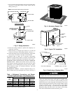
5. When passing refrigerant tubes through the wall, seal the
opening with RTV or other pliable silicon-based caulk. (See
Fig. 3.)
6. Avoid direct lineset contact with water pipes, ductwork, floor
joists, wall studs, floors, and walls.
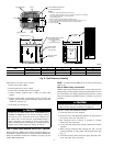
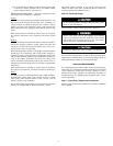
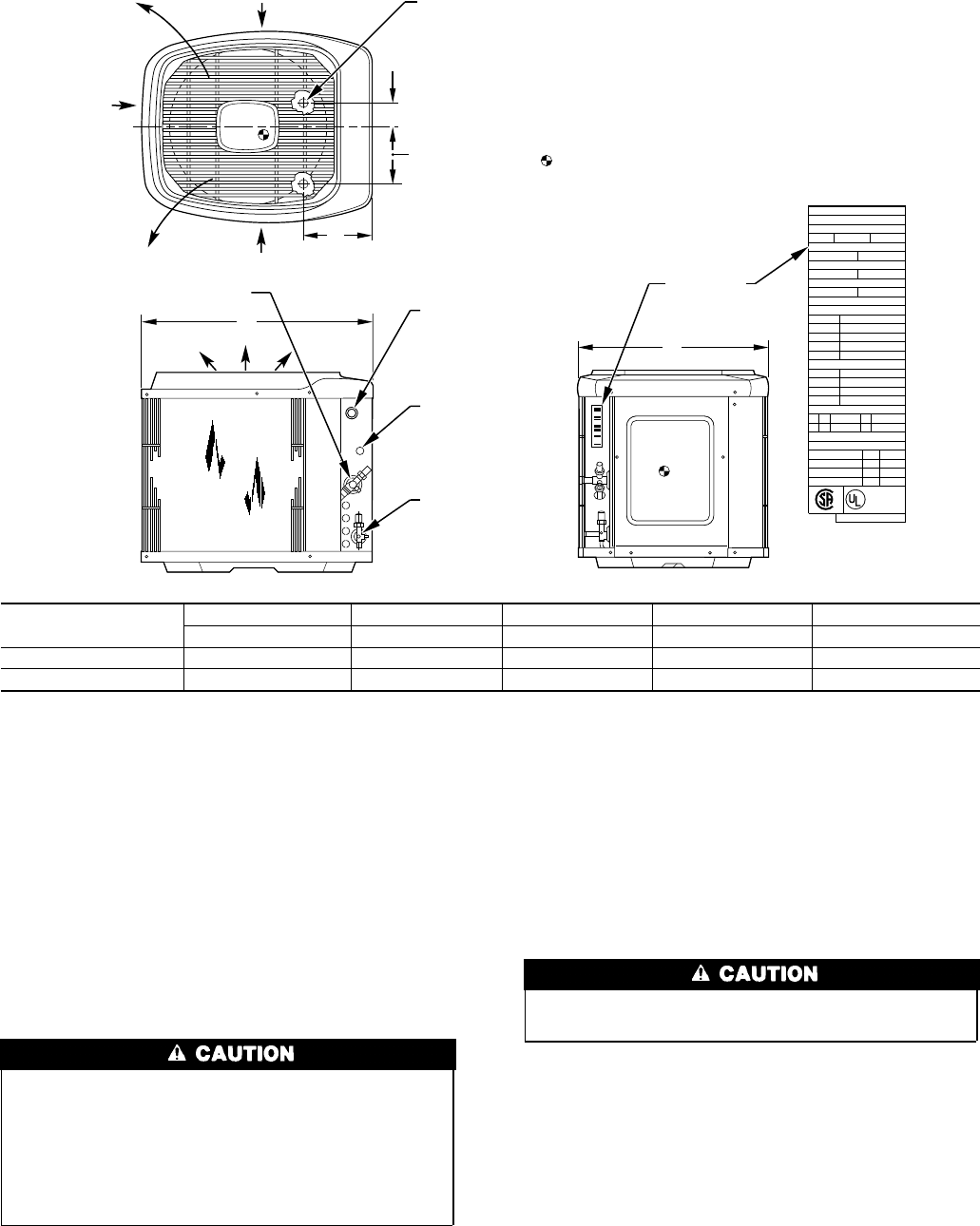
Fig. 2—Unit Reference Drawing
UNIT
SIZE
ABCD E
In. In. In. In. In.
→ 018-048 34-15/16 30 8-3/16 4 9-3/4
060 45 38-5/8 8-9/16 5-15/16 11-13/16
A92471
AIR DISCHARGE
3
/
8
IN. DIA LIQUID
LINE CONN
FIELD CONTROL
SUPPLY CONN
7
/
8
IN. DIA HOLE
AIR DISCHARGE
AIR DISCHARGE
AIR IN
AIR IN
3
/8
"
DIA TIEDOWN KNOCKOUTS
(2) PLACES IN BASEPAN
C
L
UNIT RATING
PLATE
1. Allow 30
in. (762 mm) clearance to service end of
unit, 48
in. (1219 mm) above unit, 6
in. (152 mm) on one side, 12
in. (305 mm)
on remaining side, and 24
in. (610 mm) between
units for proper airflow.
2. Minimum outdoor operating ambient in cooling mode is
55° F (12.8° C) (unless low ambient control is used) max 125° F (51.7° C).
5. Series designation is the 13th position of the unit model number.
6. Center of gravity
NOTES:
ACCESS
PANEL
FIELD POWER SUPPLY CONN
7
/
8
IN. DIA HOLE WITH
1
1
/
8
IN. DIA KNOCKOUT
AND
1
3
/
8
IN. DIA KNOCKOUT
A
C
AIR IN
E
D
B
VAPOR LINE CONN
INDIANAPOLIS IN
46206313948-401 REV A
MAX CKT-BKR
MAX HACR CKT-BKR
MAX FUSE
TYPE
MINIMUM CIRCUIT AMPS
LO
HI
DESIGN/TEST PRESSURE GAGE
FLA
HZ
PH
VOLTS AC
LRA
RLA
HZ
PH
VOLTS AC
MAX
PH
LBS
PISTON
MODEL
PROD
SERIAL
N/A
USA
N/A
CANADA
MAX OVERCURRENT PROTECTIVE DEVICE
kPa
kPa
PSI
PSI
FAN MOTOR
COMPRESSOR
SUITABLE FOR OUTDOOR USE
MIN
HZ
Kg
VOLTSPOWER SUPPLY
ID OD
FACTORY CHARGED R-22
®
®
PERMISSIBLE VOLTAGE AT UNIT
CARRIER CORP
2