


A brazing shield MUST be used when tubing sets are being
brazed to the service valves to prevent damage to the painted
unit surface.
Relieve pressure and recover all refrigerant before system
repair or final unit disposal to avoid personal injury or death.
Use all service ports and open all flow-control devices,
including solenoid valves.
Do not vent refrigerant to atmosphere. Recover during system
repair or final unit disposal.
Step 7—Make Electrical Connections
To avoid personal injury or death, do not supply power to unit
with compressor terminal box cover removed.
Be sure field wiring complies with local and national fire, safety,
and electrical codes, and voltage to system is within limits shown
on unit rating plate. Contact local power company for correction of
improper voltage. See unit rating plate for recommended circuit
protection device.
According to NEC, ANSI/NFPA 70, and local codes, the
cabinet must have an uninterrupted or unbroken ground to
minimize personal injury if an electrical fault should occur.
The ground may consist of electrical wire or metal conduit
when installed in accordance with existing electrical codes.
Failure to follow this warning could result in an electric
shock, fire, or death.
NOTE: Operation of unit on improper line voltage constitutes
abuse and could affect unit reliability. See unit rating plate. Do not
install unit in system where voltage or phase imbalance may
fluctuate above or below permissible limits.
NOTE: Use copper wire only between disconnect switch and
unit.
NOTE: Install branch circuit disconnect per NEC of adequate
size to handle unit starting current. Locate disconnect within sight
from and readily accessible from unit, per Section 440-14 of NEC.
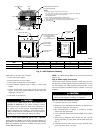
ROUTE GROUND AND POWER WIRES — Remove access
panel and control box cover to gain access to unit wiring. Extend
wires from disconnect through power wiring hole provided and
into unit control box. (See Fig. 2.)
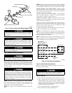
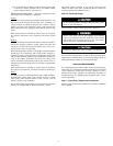
CONNECT GROUND AND POWER WIRES — Connect ground
wire to ground connection in control box for safety. Connect
power wiring to contactor as shown in Fig. 8.
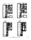
CONNECT CONTROL WIRING — Route 24-v control wires
through control wiring grommet and connect leads to control
wiring terminal board. (See Fig. 9.)
Use No. 18 AWG color-coded, insulated (35° C minimum) wires.
If thermostat is located more than 100 ft from unit (as measured
along the control voltage wires), use No. 16 AWG color-coded
wires to avoid excessive voltage drop.
Use furnace transformer, fan coil transformer, or accessory trans-
former for control power, 24-v/40va minimum.
NOTE: Use of available 24-v accessories may exceed the mini-
mum 40-va power requirement. Determine total transformer load-
ing and increase the transformer capacity or split the load with an
accessory transformer as required.
NOTE: The defrost timer is factory set for 90-minute cycles. The
timer can be field set for 30- and 50-minute cycles depending on
defrost conditions in your geographical location.
Step 8—Install Electrical Accessories
Refer to the individual instructions packaged with the kits or
accessories when installing.
Damage may occur to the scroll compressor if operated at a
negative suction pressure during a system pumpdown.
Step 9—Start-Up
1. Fully back seat (open) liquid and vapor tube service valves.
2. Unit is shipped with valve stem(s) front seated and caps
installed. Replace stem caps after system is opened to refrig-
erant flow (back seated). Replace caps finger tight and tighten
additional 1/12 turn using a backup wrench on valve body flats
to prevent distortion of sheet metal.
3. Close electrical disconnects to energize system.
4. Set room thermostat at desired temperature.
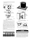
→ Fig. 7—Service Valve with Sweat Adapter Tube
A92464
LIQUID SERVICE VALVE
PISTON RETAINER
INSIDE STRAINER
PISTON
FLARE NUT
FLARE ADAPTER
→ Fig. 8—Line Power Connections
A94025
DISCONNECT
PER N.E.C. AND/OR
LOCAL CODES
CONTACTOR
GROUND
LUG
FIELD GROUND
WIRING
FIELD POWER
WIRING
BLUE
3 PHASE ONLY
4