


8
INSTALL ALL P OWER AND INTERCONNECTING WIRING TO OUTDOOR UNITS
1. Mount outdoor power disconnect.
2. Run power wiring from main box to disconnect per NEC
and local codes.
3. Remove field wiring cover from unit by loosening screws.
4. Remove caps on conduit panel.
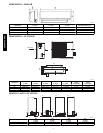
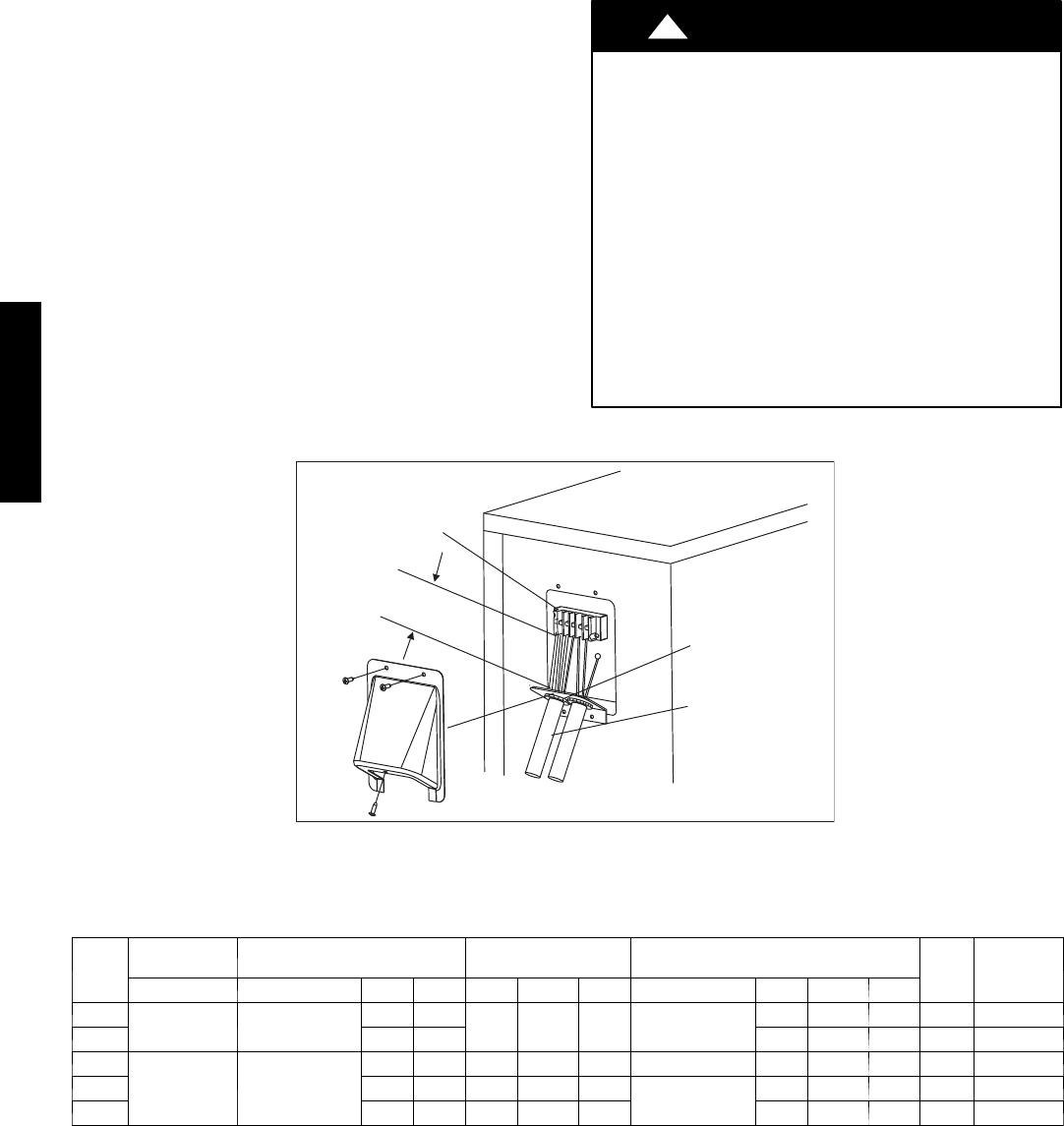
5. Connect conduit to conduit panel. (See Fig.12 )
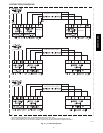
6. Properly connect both power supply and control lines to ter-
minal block per the connection diagram for the appropriate
unit capacity and voltage. (See Fig. 13, pg. 9.)
7. Ground unit in accordance with NEC and local electrical
codes.
8. Use lock nuts to secure conduit.
9. Reinstall field wiring cover.
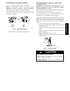
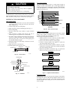
CAUTION
!
EQUIPMENT DAMAGE HAZARD
Failure to follow this caution may result in equipment
damage or improper operation.
S Be sure to comply with local codes while running wire
from indoor unit to outdoor unit.
S Every wire must be connected firmly. Loose wiring may
cause terminal to overheat or result in unit malfunction.
A fire hazard may also exist. Therefore, be sure all wiring
is tightly connected.
S No wire should be allowed to touch refrigerant tubing,
compressor or any moving parts.
S Disconnecting means must be provided and shall be
located within sight and readily accessible from the air
conditioner.
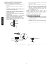
S Connecting cable with conduit shall be routed through
hole in the conduit panel.
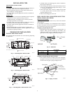
G
Over 1.57" (40mm)
Terminal Block
Conduit panel
Conduit
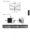
Outdoor unit
A07455
Fig. 12 --- Field Wiring
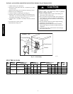
ELECTRICAL DATA
UNIT
SIZE
OPERATING
VOLTAGE
COMPRESSOR OUTDOOR FAN INDOOR FAN
MCA
MAX
FUSE/CB
AMP
MAX/MIN VOLTS --- P H --- HZ RLA LRA FLA HP W VOLTS FLA HP W
009
127/104 115 --- 1 ---60
7.5 40
0.69 0.102 23 35 D C
1.1 0.034 20 12 20
012 9.9 47 1.18 0.044 25 15 25
012
253/187 208/230---1---60
5.2 21 0.38 0.116 36 35 DC 1.18 0.044 25 9 15
018 7.3 32.6 0.78 0.224 53
208/230---1---60
0.26 0.075 31 11 20
024 9.7 34.8 0.62 0.218 100 0.39 0.112 50 14 25
38/40MVC, MVQ