


10
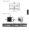
INSTALL ALL P OWER, INTERCONNECTING
WIRING, AND PIPING T O INDOOR UNIT.
1. Run interconnecting piping and wiring from outdoor unit to
indoor unit.
2. Run interconnecting cable through hole in wall (outside to
inside).
3. Lift indoor unit into position and route piping and drain
through hole in wall (inside to outside). Fit interconnecting
wiring into back side of indoor unit.
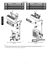
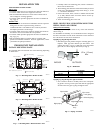
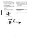
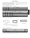
4. Put upper claw at back of indoor unit on upper hook of
Mounting Plate, move indoor unit from side to side to see
that it is securely hooked.
5. Open front cover of indoor unit and remove field wiring ter-
minal block cover.
6. Pull interconnecting wire up from back of indoor unit and
position i n close to the terminal block on indoor unit.
7. Push lower part of indoor unit up on wall, then move in-
door unit from side to side, up and down to check if it is
hooked securely. (See Fig. 14.)
Upper hook
Lower hoo
k
A07347a
Fig. 14 --- Indoor Unit Installation
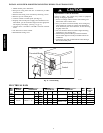
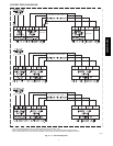
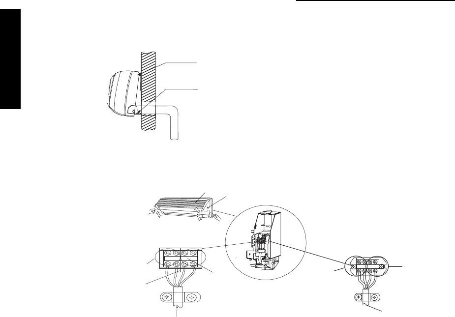
8. Connect wiring from outdoor unit per connection diagram
(see Fig. 13 and Fig. 15).
9. Replace field wiring cover and close front cover of indoor
unit.
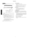
10. Connect refrigerant piping and drain line outside of indoor
unit. Refer t o Fig. 1 1 for proper installation of flare
connections. Complete pipe insulation at flare connection
then fasten piping and wiring to the wall as required. Com-
pletely s eal the hole in the wall.
NOTE: For applications where gravity cannot be used for
drainage, a condensate pump accessory is available. Consult the
condensate pump Installation Instructions for more information.
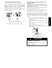
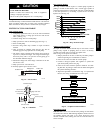
REMOTE CONTROL I NSTALLATION
Mounting Bracket (if installed on the wall)
1. Use the two screws supplied with control to attach Mount-
ing Bracket to wall in location selected by customer and
within operating range.
2. Install b atteries in Remote Control.
3. Place Remote Control into remote control Mounting Brack-
et.
4. For remote control operation, refer to the unit Owner’s
Manual.
L1 L2 S G
To outdoor unit
Panel
Terminal block
Control Box Cover
208/230-1-60
From outdoor unit
to indoor unit
Control:
Pulse DC between outdoor
unit and indoor unit with a
potential AC voltage shock hazard.
Barrier between
high and low voltage
18k & 24k
Terminal block of indoor unit
1234
To Outdoor Unit
12v DC from outdoor unit
to indoor unit
35v DC from
outdoor to indoor
9k & 12k
A07349a
Fig. 15 --- Control and Power Wiring on Indoor Unit
38/40MVC, MVQ