


3
SAFETY CONSIDERATIONS
Installing, starting up, and servicing air--conditioning equipment
can be hazardous due to system pressures, electrical components,
and e quipment location (roofs, elevated structures, etc.).
Only trained, qualified installers and service mechanics should
install, start--up, and service this equipment.
Untrained personnel can perform basic maintenance functions such
as cleaning coils. All other operations should be performed by
trained service personnel.
When working on the equipment, observe precautions in the
literature and on tags, stickers, and labels attached to the
equipment.
Follow all safety codes. Wear safety glasses and work gloves. Keep
quenching cloth and fire extinguisher nearby when brazing. Use
care in handling, rigging, and setting bulky equipment.
Read these instructions thoroughly and follow all warnings or
cautions included in literature and attached to the unit. Consult
local building codes and National Electrical Code (NEC) for
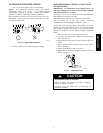
special requirements. Recognize safety information. This is the
safety--alert symbol
!
!
. When you see this symbol on the unit and
in instructions or manuals, be alert to the potential for personal
injury.Understand these sig nal words: DANGER, WARNING, an d
CAUTION. These words are used with the s afety--a lert symbol.
DANGER identifies the most serious hazards which will result in
severe personal injury or death. WARNING signifies hazards
which could result in personal injury or death. CAUTION is used
to identify unsafe practices which may result in minor personal
injury or product and property damage. NOTE is used to highlight
suggestions which will result in enhanced installation, reliability, or
operation.
!
WARNING
ELECTRICAL SHOCK HAZARD
Failure to follow this warning could result in personal
injury or death.
Before installing, modifying, or servicing system, main
electrical disconnect switch must be in the OFF
position. There may be more than 1 disconnect switch.
Lock out and tag switch with a suitable warning label.
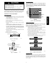
CAUTION
!
EQUIPMENT DAMAGE HAZARD
Failure to follow this caution may result in equipment
damage or improper operation.
Do not bury more than 36 in. (914 mm) of refrigerant pipe
in the ground. If any section of pipe is buried, there must be
a 6 in. (152 mm) vertical rise to the valve connections on
the outdoor units. If more than the recommended length is
buried, refrigerant may migrate to the cooler buried section
during extended periods of system shutdown. This causes
refrigerant slugging and could possibly damage the
compressor at start--up.
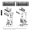
GENERAL
These instructions cover the installation, start --up and servicing of
38MVC,MVQ outdoor and 40MVC, MVQ indoor units duct free
systems.
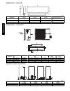
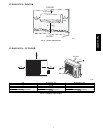
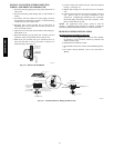
SYSTEM REQUIREMENTS
Allow sufficient space for airflow and servicing unit. See Fig. 3
and 4 for minimum required distances between unit and walls or
ceilings.
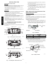
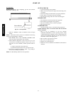
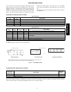
Piping
IMPORTANT: Both refrigerant lines must be insulated
separately.
S Minimum refrigerant line length between the indoor and outdoor
units is 10 ft. ( 3 m).
S The following maximum lengths are allowed:
REFRIGERANT LINE LENGTHS ft. (m)
Unit Size Max Line Length
Max Elevation
(ID over OD)
Max Elevation
(OD over ID)
9K 65 (20) 35 (11) 35 (11)
12K 65 (20) 35 (11) 35 (11)
18K 100 (30) 50 (15) 50 (15)
24K 100 (30) 60 (18) 60 (18)
S The following are the piping sizes.
PIPE SIZES
Unit Size Mix P h ase Vapor
9K 1/4” 3/8”
12K 1/4” 1/2”
18K 1/4” 1/2”
24K 3/8” 5/8”
Refrigerant Charge
REFRIGERANT CHARGE lb. (kg)
Unit Size Air Conditioner
Heat Pump
9K 2.3 (1.0) 2.4 (1.1)
12K 2.9 (1.3) 3.0 (1.4)
18K 4.4 (2.0) 4.5 (2.0)
24K 5.3 (2.4) 5.3 (2.4)
S Above charge is for piping runs up to 25 ft. (7.6 m).
S For piping runs greater than 25 ft. (7.6 m), add 0.1 oz. of
r efrigerant per f oot of extra piping up to the allowable
length.
S Capillary tubes i n outdoor unit are used as metering devices.
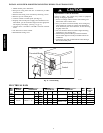
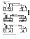
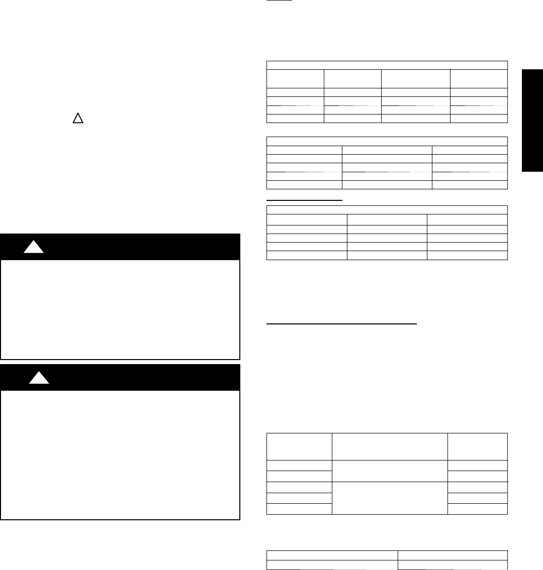
Connecting (Power and Control
Cable)
S The main power is supplied to the outdoor unit. The field
supplied connecting cable from the outdoor unit to indoor unit
consists of four wires and provides the power for the indoor unit
as well as the communication signal between the outdoor and
indoor unit.
For 9K and 12K units, all four wires are low voltage DC.
For 18K and 24K, two wires are high voltage AC power, one is
pulse DC and one is a ground wire.
S Consult local building codes, NEC (National Electrical Code) or
CEC (Canadian Electrical Code) for special requirements.
Model Size Power Source
MIN CKT AMP
MAX FUSE/CB
AMP
9k
115 --- 1 ---60
12/20
12k 15/25
12k
208/230---1---60
9/15
18k 11/20
24k 14/25
S Connecting Cable: Voltage drop on the connecting cable
should be kept to a minimum. Do not use thermostat wire. Use
cable size and max length below:
18 AWG 50 Feet (16 m)
16 AWG 100 Feet (33 m)
38/40MVC, MVQ