


6
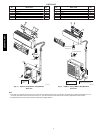
INSTALLATION TIPS
Ideal installation locations include:
Indoor
Unit
S A location where there a re no obstacles near inlet a nd outlet area.
S A location which can bear the weight of indoor unit.
S Do not install indoor units near a direct source of heat such as
direct sunlight or a heating appliance.
S A location which provides appropriate clearances as outlined in
Fig. 3 (pg. 5).
Outdoor
Unit
S A location which is convenient to installation and not exposed to
strong wind. If unit is exposed to strong winds it is
recommended that a wind baffle be used. Contact your Duct
Free Split representative for drawings.
S A location which can bear the weight of outdoor unit and where
the outdoor unit can be mounted in a level position.
S A location which provides appropriate clearances as outlined in
Fig. 4 (pg. 5).
S Do not install the indoor or outdoor units in a location with
special environmental conditions. For those applications, contact
your Duct Free Split representative.
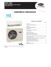
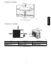
INDOOR UNIT INSTA LLATION
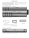
INSTALL MOUNTING PLATE
The mounting plate will look like one of the following depending
on model size:
4.72" (120) or more
to wall
Right rear side
refrigerant
pipe hole o 65
5.20"
(132)
3.54"
(90)
Mounting Plate
6"(152) min. to ceiling
23.50"(597)
3.19" (81)
1.77"(45)
32.09" (815)
11.10" (282"
Indoor unit outline
4.72" (120)
or more to wall
Left rear side
refrigerant
pipe hole o 65
1.77"
(45)
1.77"
(45)
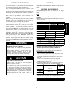
NOTE: Measurements in ( ) are in mm.
6'(1.8 m) min. to floor
A07338
Fig. 5 --- Mounting Plate-- Model size 009
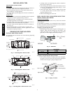
Rear-left pipe
hole o 65mm
Indoor unit outline
6" (152) min.
to ceiling
Mounting Plate
4.72" (120)
or more to wall
Rear-left pipe
hole o 65mm
32.01" (813)
1.57" (40)
2.05" (52)
35.63" (905)
11.26" (286)
1.99" (50)
3.54" (90)
3.86" (98)
5.00" (127)
2.17" (55)
1.99" (50)
4.72" (120)
or more to wall
6' (1.8 m) min.
to floor
A07339
Fig. 6 --- Mounting Plate-- Model size 012
Indoor unit outline
Pipe hole
Pipe hole
12.80" (325)
95
10.12" (257)
32.09" (815)
7.01"
(178)
49.21" (1250)
95
6" (152) min. from ceiling
Hooked Part Hooked Part
Above 4.72" (120)
from the wall
2.17" (55)
2.17" (55)
2.17" (55)
2.28" (58)
A
bove 4.72" (120)
from the wall
Mounting Plate
6' (1.8 m) min. to floor
A07340
Fig. 7 --- Mounting Plate-- Model sizes 018 -- 024
1. Carefully remove the mounting plate, which is attached to
the back of the indoor unit.
2. The mounting plate should be located horizontally and level
on the wall. All minimum spacings shown in Fig. 3, 4, and
5 -- 7 should be maintained.
3. If the wall is block, brick, concrete or similar material, drill
.2” (5 mm) diameter holes and insert anchors for the ap-
propriate mounting screws.
4. Attach the mounting plate to the wall.
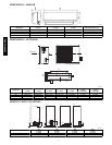
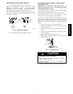
DRILL HOLE I N WALL FOR INT ERCONNECTING
PIPING, DRAIN AND W IRING
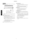
Refrigerant Line Ro uting
The refrigerant lines may be routed in any of the four directions
showninFig.9.
For m aximum serviceability, it is recommended to have refrigerant
line flare connections and the drain connections on the outside of
the wall that the fan coil can be mounted on.
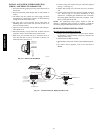
If piping is going through the back:
1. Determine pipe hole position using the mounting plate as a
template. Drill pipe hole diameter per chart below. The
outside pipe hole is 1/2--in. (13 mm) min. lower than inside
pipe hole, so it slants slightly downward (see Fig. 8).
1/2 in. (13 mm)
Min.
INDOOR
OUTDOOR
A07371
Fig. 8 --- Drill Holes
Model Size
Hole Diameter
in. (mm)
009, 012 2.75 (70)
018, 024 3.75 (95)
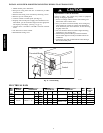
If piping is going through the right or left side:
1. Use a small saw blade to carefully remove the correspond-
ing plastic covering on side panel and drill the appropriate
size hole where the pipe is going through the wall.
Pipe holder
Pipe cover
Right piping
Left piping
Pipe cover
Right back piping
Left back piping
1
2
3
4
Size 012
Only
A07344
Fig. 9 --- Piping Locations
38/40MVC, MVQ