


NOTE: Use of available 24-v accessories may exceed the mini-
mum 40-va power requirement. Determine total transformer load-
ing and increase the transformer capacity or split the load with an
accessory transformer as required.
Step 9—Compressor Crankcase Heater
When equipped with a crankcase heater, furnish power to heater a
minimum of 24 hr before starting unit. To furnish power to heater
only, set thermostat to OFF and close electrical disconnect to
outdoor unit.
A crankcase heater is required if refrigerant tubing is longer than
50 ft.
NOTE: The Seasonal Energy Efficiency Ratio (SEER) is ob-
tained with crankcase heater de-energized. To de-energize crank-
case heater, disconnect black crankcase heater wires at contactor.
After disconnecting, make sure wires are isolated from all other
electrical connections and components to prevent electrical short-
ing.
Step 10—Install Electrical Accessories
Refer to the individual instructions packaged with kits or acces-
sories when installing.
Step 11—Start-Up and Check Charge
To prevent compressor damage or personal injury, observe
the following:
• Do not overcharge system with refrigerant.
• Do not operate unit in a vacuum or at negative pressure.
• Do not disable low-pressure switch
In scroll compressor applications:
• Dome temperatures may be hot.
• In 3 phase application, incorrect phasing will cause reverse
rotation, resulting in elevated noise levels, equalized pres-
sures, and reduced current draw. Correct by reversing power
connection L1 and L2 on contactor.
To prevent personal injury wear safety glasses, protective
clothing, and gloves when handling refrigerant and observe
the following:
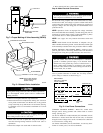
• Back seating service valves are not equipped with Schrader
valves. Fully back seat (counter clockwise) valve stem before
removing gage port cap.
• Front seating service valves are equipped with Schrader
valves.
Do not vent refrigerant to atmosphere. Recover during system
repair or final unit disposal.
Follow these steps to properly pumpdown a system and avoid
negative suction pressure.
1. Fully back seat (open) liquid and vapor tube service valves.
2. Unit is shipped with valve stem(s) front seated (closed) and
caps installed. Replace stem caps after system is opened to
refrigerant flow. Replace caps finger-tight and tighten with
wrench an additional 1/6-turn for front seating valves (female
hex stem) or 1/12 turn for back seating valves (male square
stem).
3. Close electrical disconnects to energize system.
4. Set room thermostat at desired temperature. Be sure set point
is below indoor ambient temperature.
5. Set room thermostat to COOL and fan to FAN or AUTO
mode, as desired. Operate unit for 15 minutes. Check system
refrigerant charge.
6. Factory charge is shown on unit rating plate. Adjust charge by
following procedure shown on charging tables located on unit.
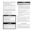
SEQUENCE OF OPERATION
Turn on power to indoor and outdoor units. Transformer is
energized.
On a call for cooling, thermostat makes circuits R-Y and R-G.
Circuit R-Y energizes contactor, starting outdoor fan motor and
compressor circuit. R-G energizes indoor unit blower relay,
starting indoor blower motor on high speed.
When thermostat is satisfied, its contacts open, de-energizing
contactor and blower relay. Compressor and motors stop.
If indoor unit is equipped with a time-delay relay circuit, the
indoor blower will run an additional 90 sec to increase system
efficiency.
CARE AND MAINTENANCE
For continued high performance and to minimize possible equip-
ment failure, periodic maintenance must be performed on this
equipment.
Leave User’s Manual with homeowner. Explain system operation
and periodic maintenance requirements outlined in manual. Fre-
quency of maintenance may vary depending on geographic areas,
such as coastal applications which require more frequent mainte-
nance.
5