


Wiring must comply with local codes and NEC requirements,
if a field-supplied control power source is needed when
adding solenoid.
1. Remove coil liquid connection cap and discard.
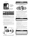
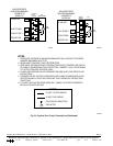
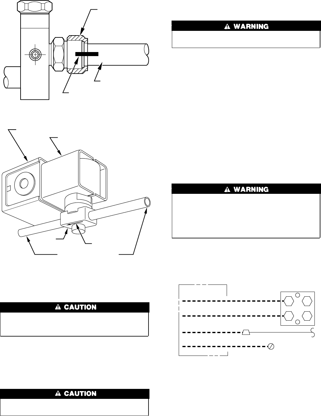
2. Mount solenoid valve on liquid tube, making sure valve flow
arrow points toward indoor coil. Mount valve in any position
except valve body at top and electric coil at bottom. (See Fig.
8.) Solenoid valve is to be installed a maximum of 2 ft from
indoor coil.
Avoid valve damage while brazing by wrapping valve with a
heat-sinking material such as a wet cloth.
3. Braze valve onto end of liquid tube using silver bearing or
non-silver bearing brazing material. Consult local code re-
quirements.
4. Braze flare adapter onto outlet end of solenoid valve.
5. Wire solenoid coil into system control circuit.
Step 8—Make Electrical Connections
To avoid personal injury or death, do not supply power to unit
with compressor terminal box cover removed.
Be sure field wiring complies with local and national fire, safety,
and electrical codes, and voltage to system is within limits shown
on unit rating plate. Contact local power company for correction of
improper voltage. See unit rating plate for recommended circuit
protection device.
NOTE: Operation of unit on improper line voltage constitutes
abuse and could affect unit reliability. See unit rating plate. Do not
install unit in system where voltage or phase imbalance (3 phase)
may fluctuate above or below permissible limits.
NOTE: Use copper wire only between disconnect switch and
unit.
NOTE: Install branch circuit disconnect of adequate size per
NEC to handle unit starting current. Locate disconnect within sight
from and readily accessible from unit, per Section 440-14 of NEC.
ROUTE GROUND AND POWER WIRES — Remove access
panel to gain access to unit wiring. Extend wires from disconnect
through power wiring hole provided and into unit control box.
The unit cabinet must have an uninterrupted or unbroken
ground to minimize personal injury if an electrical fault
should occur. The ground may consist of electrical wire or
metal conduit when installed in accordance with existing
electrical codes. Failure to follow this warning can result in an
electric shock, fire, or death.
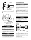
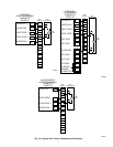
CONNECT GROUND AND POWER WIRES — Connect ground
wire to ground connection in control box for safety. Connect
power wiring to contactor as shown in Fig. 9.
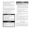
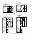
CONNECT CONTROL WIRING — Route 24-v control wires
through control wiring grommet and connect leads to control
wiring. (See Fig. 10.)
Use No. 18 AWG color-coded, insulated (35°C minimum) wire. If
thermostat is located more than 100 ft from unit, as measured
along the control voltage wires, use No. 16 AWG color-coded wire
to avoid excessive voltage drop.
Use furnace transformer, fan coil transformer, or accessory trans-
former for control power, 24-v/40-va minimum.
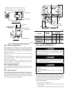
Fig. 7—Proper Marking of Valve Assembly (38CKQ)
A92122
LOCK NUT
MARK ON LOCK NUT
AND TUBE
TUBING
Fig. 8—Solenoid Valve Installation
A87044
ELECTRICAL JUNCTION
ELECTRICAL COIL
VALVE
FLOW ARROW
STRAIGHT
3
/
8
IN. STUD
NOTE:System flow direction
must match arrow on
bottom of body.
Fig. 9—Line Power Connections
A94025
DISCONNECT
PER N.E.C. AND/OR
LOCAL CODES
CONTACTOR
GROUND
LUG
FIELD GROUND
WIRING
FIELD POWER
WIRING
BLUE
3 PHASE ONLY
4