


4. After wrapping service valve with a wet cloth, tubing set can
be brazed to service valve using either silver bearing or
non-silver bearing brazing material.
5. Refrigerant tubing and indoor coil are now read for leak
testing. This check should include all field and factory joints.
MECHANICAL CONNECTION (38CKQ MODELS)
1. Cut tubing to correct length, deburr, and size as necessary,
making sure tube ends are square. If a large burr is evident, ID
and OD must be deburred to allow tube to bottom in valve.
2. Remove lock nuts and ferrules from plastic bags taped to
service panel. (See Fig. 5.)
If undersized, damaged, or elliptically shaped tubing is used
when making connection, leaks could result.
3. Slide lock nut and ferrule onto each tube. (See Fig. 6.)
4. Apply a few drops of refrigerant oil to ferrule and valve
threads to reduce assembly torque and assist sealing.
5. Insert tube end into service valve until it bottoms.
6. Push ferrule into place and hand tighten nut until an increase
in torque is felt.
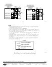
7. Mark nut and tube and tighten 1-1/2 turns from mark. (See
Fig. 7.) Keep tube bottomed in valve while tightening nut.
NOTE: A backup wrench on the hex part of the suction valve is
required while tightening.
The tube end must stay bottomed in the service valve during
final assembly to ensure proper seating, sealing, and rigidity.
MECHANICAL FITTING REPAIR
To replace damaged ferrule or tubing proceed as follows.
1. Attach gages to service valves.
2. Close liquid service valve and operate unit to pump refrigerant
charge into condenser coil.
3. When suction pressure reaches 5 psig, shut unit off. Do not
operate unit in a vacuum.
4. Close suction service valve and recover refrigerant in tubing.
5. Back-off locknut and ferrule onto tube.
6. Remove damaged part of tubing using tubing cutter. Repeat
installation procedure previously outlined using new ferrule.
7. Evacuate tubing set and indoor coil. Check for leaks.
8. Open service valves or recharge unit. Check refrigerant
charge.
Step 7—Install Solenoid Valve In Liquid Tube (If Re-
quired)
Not all applications require use of a liquid tube solenoid
valve. If your unit has been shipped with a liquid tube
solenoid valve in the unit, it must be installed for performance
enhancement. The liquid tube solenoid valve must be ener-
gized during evacuation for complete removal of refrigerant.
Before making liquid tube connections, install factory-supplied
solenoid valve on indoor liquid fitting. (See Fig. 8.) Be sure to use
flare adapter supplied with the indoor coil when making connec-
tions.
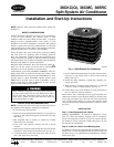
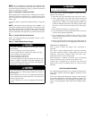
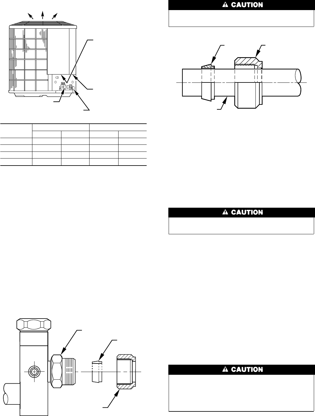
Fig. 4—Refrigerant Tube Dimensions/Connections
UNIT SIZE
LIQUID TUBE VAPOR TUBE
Conn Dia Tube Dia Conn Dia Tube Dia
018, 024 3/8 3/8 5/8 5/8
030, 036 3/8 3/8 3/4 3/4
042, 048 3/8 3/8 7/8 7/8
060 3/8 3/8 7/8 1-1/8
NOTE: Tube diameters are for lengths up to 50 ft. For tubing lengths greater
than 50 ft, consult your local distributor.
If refrigerant tubing or indoor coil is exposed to atmosphere, it
must be evacuated to a minimum of 500 microns to eliminate
contamination and moisture in the system.
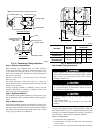
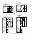
A97009
LIQUID LINE CONN
FIELD CONTROL
SUPPLY CONN
7
⁄
8
″ DIA HOLE
FIELD POWER
SUPPLY CONN
7
⁄
8
″ DIA HOLE WITH
1
1
⁄
8
″ DIA KNOCKOUT
AND
1
3
⁄
8
″ DIA
KNOCKOUT
AIR DISCHARGE
SUCTION LINE CONN
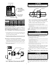
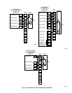
Fig. 5—Mechanical Fitting Assembly (38CKQ)
A92120
VALVE FITTING
FERRULE
LOCK NUT
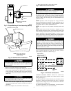
Fig. 6—Lock Nut/Ferrule Positioning (38CKQ)
A92121
FERRULE LOCK NUT
TUBING
3