


Step 3—Clearance Requirements
When installing, allow sufficient space for airflow clearance,
wiring, refrigerant piping, and service. Common clearances are 6
in. on 1 side, 12 in. on 2 sides, and 30 in. on service side of unit.
Allow 24 in. between units. Discharge air must be unobstructed
and must not recirculate.
Position so water, snow, or ice from roof or eaves cannot fall
directly on unit.
On rooftop applications, locate unit at least 6 in. above roof
surface. Place unit above a load-bearing wall and isolate unit and
tubing set from structure.
Arrange supporting members to adequately support unit and
minimize transmission of vibration to building. Consult local
codes governing rooftop applications.
Step 4—Operating Ambients
The minimum outdoor operating ambient in cooling mode is 55°F,
and the maximum outdoor operating ambient in cooling mode is
125°F.
Step 5—Metering Device
If unit is being installed with piston, check indoor coil piston to see
if it matches the required piston shown on outdoor unit rating plate.
If it does not match, replace indoor coil piston with piston shipped
with outdoor unit. The piston shipped with outdoor unit is correct
for any approved indoor coil combination.
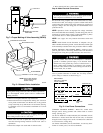
Step 6—Make Tubing Connections
Relieve pressure and recover all refrigerant before system
repair or final unit disposal to avoid personal injury or death.
Use all service ports and open all flow-control devices,
including solenoid valves.
To prevent compressor damage DO NOT bury more than 36
in. of refrigerant tubing. If ANY tubing is buried, provide 6
in. vertical rise at service valve.
To prevent damage to unit or service valves observe the
following:
• Use a brazing shield.
• Wrap service valves with wet cloth or use a heat sink
material.
Connect outdoor unit to indoor sections using accessory tubing
package or field-supplied tubing of refrigerant grade, correct size,
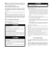
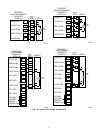
and condition. Refer to Fig. 4 for refrigerant tube dimensions and
connections. For tubing requirements beyond 50 ft, consult your
local distributor or the Long-Line Application Guideline.
SWEAT CONNECTION
1. Consult local code requirements.
2. Connect tubing to fittings on outdoor unit vapor and liquid
service valves.
3. Service valves are closed from factory and ready for brazing.
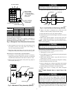
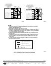
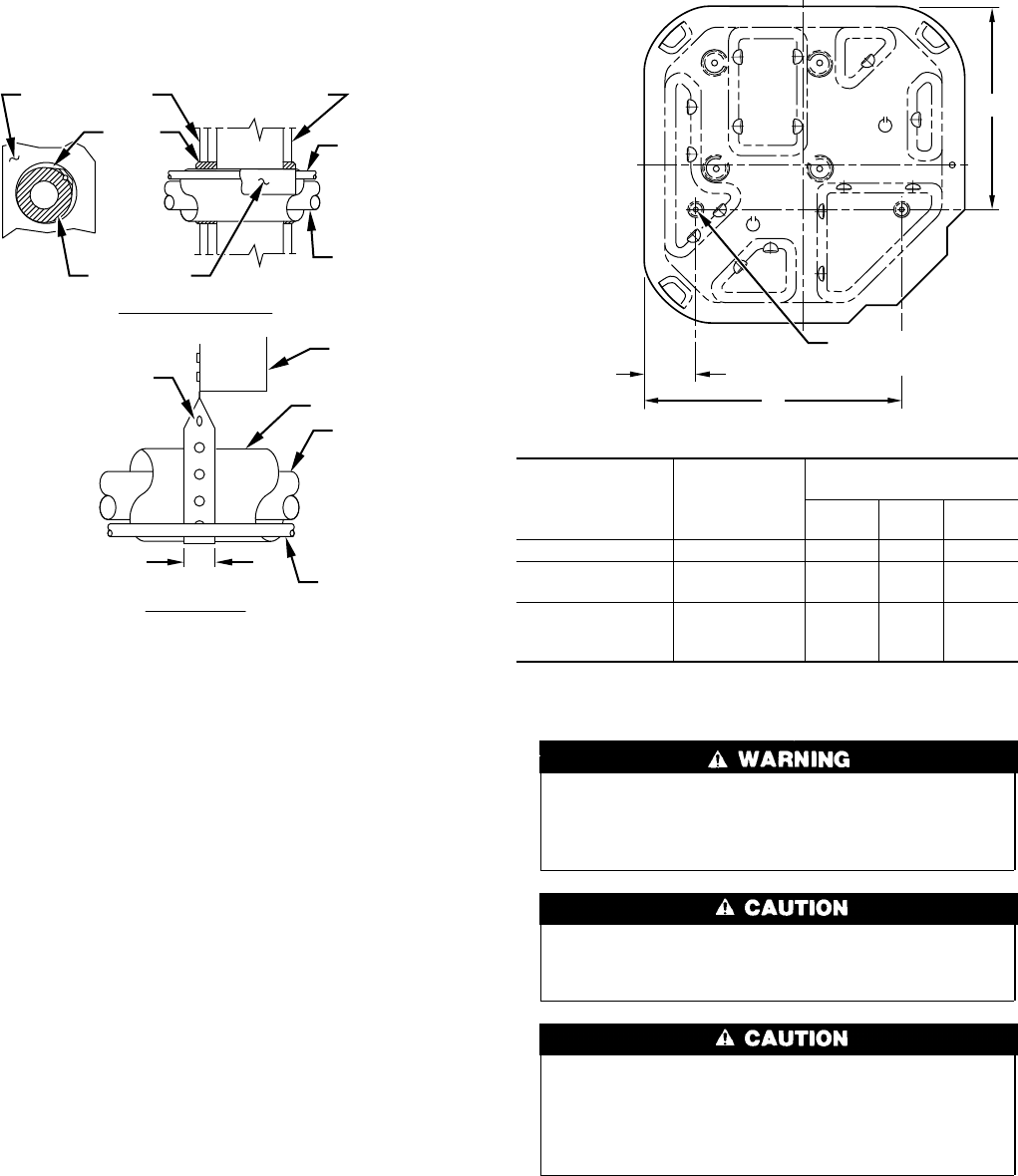
Fig. 2—Connecting Tubing Installation
A94028
INSULATION
VAPOR TUBE
LIQUID TUBE
OUTDOOR WALL INDOOR WALL
LIQUID TUBE
VAPOR TUBE
INSULATION
CAULK
Avoid contact between tubing and structureNOTE:
THROUGH THE WALL
HANGER STRAP
(AROUND VAPOR
TUBE ONLY)
JOIST
1″ MIN.
SUSPENSION
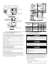
Fig. 3—Mount Unit to Pad
A94199
UNIT SIZE
MIN PAD
DIM (IN.)
TIEDOWN KNOCKOUT
LOCATIONS
A
(In.)
B
(In.)
C
(In.)
38CKC(Q)018, 024 18 X 18 3 15 10-3/16
38CKC(Q)030-042
38CMC018-030
22-1/2 X 22-1/2 3-11/16 18-1/8 14-3/8
38BRC024-060
38CKC(Q)048, 060
38CMC036-060
30 X 30 6-1/2 23-1/2 20
C
B
A
3
⁄
8
″D. (9.53) TIEDOWN
KNOCKOUTS (2) PLACES
2