


2
PREINSTALLATION
Every installer should perform site evaluation prior to
installing the transceivers. In order to perform this evaluation
the following minimum equipment must be purchased from
Carrier. The two modem starter kit (33CNWIRMOD) is re-
quired to begin performing a site evaluation. The following
components are in the two modem kit:
2 — standalone transceivers
2 — high gain omni-directional antenna
2 — transceiver power supplies
2 — RS-232 to RS-485 converters
2 — 9-pin RS-232 cables
1 — copy of transceiver configuration software
1 — loopback connector
If the set up requires outdoor antennas they can be pur-
chased from Carrier as part number 33CNOAANT1.
High gain directional antennas may be required to establish
reliable communications. Directional antennas can be pur-
chased directly from the antenna vendors described in the an-
tenna selection and location section of this manual.
Site Evaluation Testing — Loopback Test —
In
order to perform a loopback test the transceivers must be con-
figure Broadcast Remote-to-All. See the Remote-to-All config-
uration section of this manual.
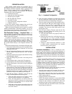
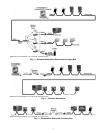
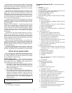
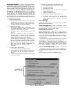
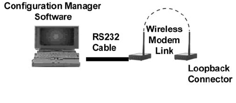
To perform a loopback test it is necessary to connect each
modem (one host and one remote) to its power supply. Then
connect a PC with the Configuration Manager software to a
modem using the 9-pin RS-232 cable provided. Lastly, connect
the second modem directly to the loopback connector. See
Fig. 1.
Perform the loopback test by executing the following steps:
1. Position the modems directly on top of each other and re-
move both modem antennas if connected. Use a host and
remote pair for this test.
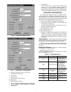
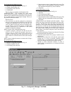
2. Run the Configuration Manager on the computer and log
into the software using the username “oem” and pass-
word “oem”.
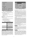
3. Select the Loopback Test program tab within the Config-
uration Manager software.
4. In the Test String dialog box enter a text string such as
TESTING.
5. Using the pointer place a check in the Test check box.
6. Using the pointer select the Instantaneous RSSI option.
7. Press the Start button on the screen to begin sending the
Test String.
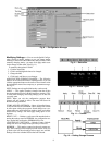
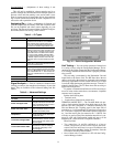
8. The TX pane should start displaying the Test String at
regular intervals. If the string is being received and sent
back by the remote transceiver the RX pane should dis-
play the same text screen. If the Test String is successfully
transmitted through the loopback connector with the
transceivers on top of each other proceed to Step 10.
9. If the RX pane displays “Timeout?” each time the Test
String is sent then perform the following tests:
a. Verify that both transceivers are properly config-
ured for Broadcast Remote-to-All operation.
b. Verify that both antennas are removed from the
transceivers (NOTE: if antennas are connected and
located too close together the two antenna fields
will cancel each other out).
c. Verify that cycling power to the modems shows the
3-flash blink as described in the Getting Status sec-
tion of this manual.
10. After successfully establishing communications between
the two transceivers locally, locate the transceivers in
their desired locations and repeat Steps 2 through 8.
11. If the text string is being received and sent back by the re-
mote transceiver the RX pane should display the same
text string. If the text string is successfully sent and
received the transceiver and antenna locations are
acceptable. The green sync light should remain lit once
the first data is sent.
12. If the RX pane displays Timeout? each time the Test
String, is sent them perform the following tests or the
sync light will not remain on:
a. Verify that both antennas are properly installed on
the transceivers.
b. Reposition the transceivers such that the green sig-
nal strength bar is as long as possible. Normally
signal strengths above .5 are required for reliable
communications (see Antenna Selection and Loca-
tion section).
c. Attempt to utilize directional antennas in order
to obtain reliable communications (see Antenna
Selection and Location section).
INSTALLATION
Hardware Installation —
Prior to installing the trans-
ceiver(s), count and check all of the delivered equipment. A
power supply and an antenna is required for each transceiver.
The transceiver will be attached to either RS-232, RS-485 con-
verter to a PC or laptop. Prior to installation on the desired de-
vice, all transceivers must first be connected to and configured
with a PC.
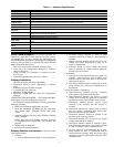
Carrier recommends mounting wireless transceivers inside
a building structure. Refer to Table 1 for temperature and
humidity criteria when mounting transceivers. If an antenna
is mounted outdoors or the CCN network extends outside of
a building, use of an RS-485 surge suppressor is recommend-
ed. Refer to CCN installation and Start-up Instructions for
lightning/surge protection recommendations.
To install the transceiver, perform the following procedure
and refer to Table 1 for hardware specifications:
1. Insert the power supply male connector into the corre-
sponding female connector slot on transceiver chassis.
2. Insert power supply plug into power (i.e., power outlet).
Verify LEDs 1 and 2 on front panel blink three times.
LED 1 should remain lit.
3. Attach the antenna to the transceiver.
NOTE: The antenna connection is a reverse thread SMA
connection. It must be turned counterclockwise to attach.
4. Attach the male connector on the RS-232 cable to the
matching serial port on the rear panel of the transceiver.
5. Connect the other end of the RS-232 cable to the match-
ing serial port on the device.
Fig. 1 — Loopback Configuration