


12
Test Communications Between Units:
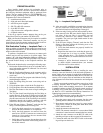
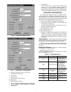
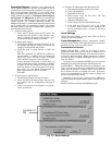
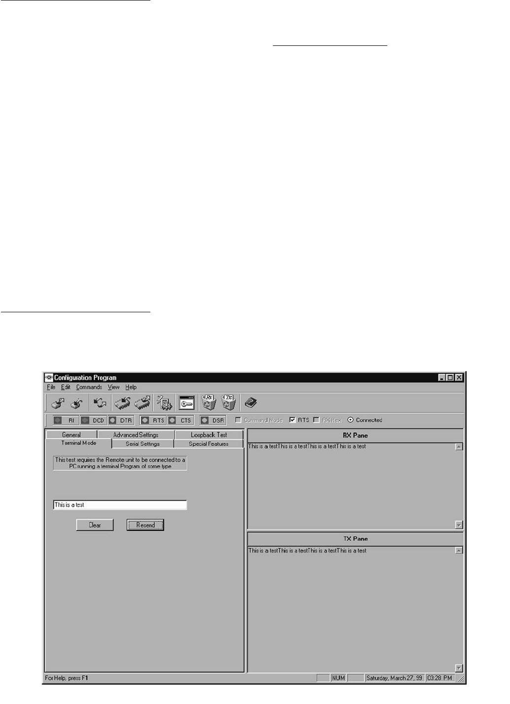
1. Open the Configuration Manager. See Fig. 17.
2. Click the Terminal Mode tab.
3. In Test String, enter some text.
4. Click Resend.
The test string is transmitted to the Destination Unit.
LOOPBACK TEST — The Loopback Test screen allows
you to perform two functions; to test that two units can com-
municate and to determine the best placement of one unit rela-
tive to another based on received signal strength. This test is
only used for stand-alone models.
What You Need:
• Two transceivers (A and B): configured as a Broadcast
Remote-to-All and Host Pair. The Source Unit ID of unit
A equals the Destination Unit ID of unit B and vice-
versa. In addition, both units must have matching Ven-
dor ID numbers, Network ID numbers and Hop Table
numbers. Transceiver A is connected to a PC loaded
with the Configuration Manager.
NOTE: Test also works with host/remote set up.
• Loopback connector: Transceiver B (the one not con-
nected to the PC running this program) must have a
loopback connector (pins 2 and 3 of the serial port tied
together) on the serial port of the remote unit. A loop-
back connector is delivered with all demo and developer
kits.
NOTE: Connect loopback connector to remote units if using a
host to remote set up.
Test Communications Between Units:
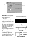
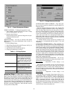
1. Open the Configuration Program. See Fig. 18.
2. Click the Loopback Test tab.
3. In Test String, enter some text.
4. Enter the desired criteria in other fields in this group. The
default values are recommended for this type of testing.
The minimum for Repeat Every field is 100 msec.
5. Click Start.
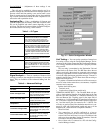
Test the Placement of a Unit:
1. Click the Loopback Test tab. See Fig. 19.
2. Click Test.
3. Click Instantaneous RSSI.
4. Enter some text in the Test String.
5. Enter the desired criteria in other fields in this group. The
default values are recommended for this type of testing.
6. Click Start.
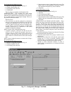
VIEWING DATA IN THE RX AND TX PANES — These
display areas show the data being transmitted and received dur-
ing tests. The RX pane shows data being received into the
transceiver. The TX pane shows data being transmitted from
the transceiver. All data sent will be displayed and at times the
pane may become cluttered. You can use the Clear buttons on
the toolbar or the commands in the Edit menu to clear the
panes of data. To clear data in the panes, select Clear RX Pane
or Clear TX Pane.
If the RX pane displays Timeout? each time the Test String
is sent then perform the following tests:
• Vertify that both antennas are properly installed on the
transceivers.
• Reposition the transceivers such that the green signal
strength bar is as long as possible. Normally signal
strengths above .5 are required for reliable communica-
tions (see Antenna Selection and Location section).
• Attempt to utilize directional antennas in order to
obtain reliable communications (see Antenna Selection
and Location).
Fig. 17 — Configuration Manager, Test Mode