


11
Session Holdoff
— (Adjustment of these settings is not
recommended.)
This will only be enabled for a host transceiver and is re-
quired to manage the communication from multiple remotes. It
prevents a host unit from starting a new session until it com-
pletes its current session. It keeps other devices from establish-
ing a session with the host until the host has completed its cur-
rent session with a particular device.
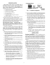
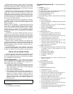
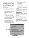
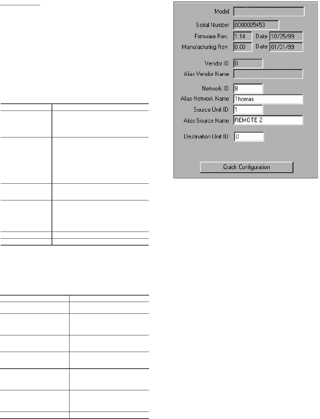
Assigning IDs —
Using a combination of firmware and
software assigned IDs, the security of the data is ensured. Some
IDs can be modified and others cannot depending on your
privileges. The IDs are all accessed either via Quick Configura-
tion or the General Tab. See Fig. 16 and Table 5.
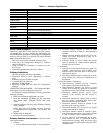
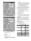
Table 5 — ID Types
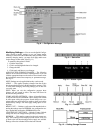
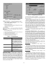
Signal Analysis —
There are a number of features which
can help you analyze the strength and consistency of your data
signal. They are available via the Advanced Settings tab. See
Table 6.
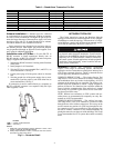
Table 6 — Advanced Settings
Unit Testing —
You can test the operation of transceivers
in a variety of ways using the Configuration Manager. The in-
structions in this section assume that the Configuration Manag-
er is correctly installed and the transceiver is properly connect-
ed to your PC.
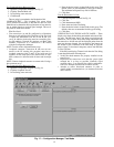
The test string is transmitted to the Destination Unit and
looped back to the Source Unit. The RX Pane shows the test
string as received by the transceiver connected to the computer
after being loopbacked from the remote transceiver. If no data
is received within the timeout period the message “Timeout” is
printed in the RX Pane. The TX Pane shows the test string as
typed in the dialogue box.
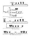
To perform a communication link test it will be necessary to
use two Carrier wireless transceivers, two antennas, a loopback
connector and a computer.
Perform the following tests:
• Terminal mode
• Loopback test (Stand-alone model only)
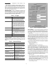
TERMINAL MODE TEST — The Terminal Mode tab pro-
vides a simple terminal interface from which data can be sent
between two units configured as a Broadcast Remote-to-All
Host and Remote Pair. Anything typed in the input field of
transceiver no. 1 will immediately be transferred to transceiver
no. 2. The data is displayed in the transmit pane for transceiver
no. 1 and the receive pane for transceiver no. 2. (NOTE: You
will only see received data if the destination transceiver is con-
nected to a PC with Configuration loaded and open or if the
destination PC’s transceiver has a loopback connector.)
What You Need:
• Two transceivers (A and B) configured as a host to
remote. The Source Unit ID of unit A equals the Desti-
nation Unit ID of unit B and vice-versa. In addition, both
units must have matching Vendor ID numbers, Network
ID numbers and Hop Table numbers.
• One of these units is connected to a PC with the Config-
uration Manager loaded.
ID TYPE EXPLANATION
Vendor ID
Assigned at the factory and burned into the
firmware. This number is not modifiable.
This ensures that no other Carrier cus-
tomer can intercept data assigned to the
ID. There are 64,000 unique Vendor IDs.
Network ID
A number that identifies the network and
makes it unique from other networks in the
area. All units in a network must have the
same Network ID. The Network ID allows
the user to have multiple networks within
the same transceiver space. There are up
to 64,000 unique numbers. Units with dif-
ferent IDs cannot communicate with each
other.
Source Unit ID
For broadcast network communication, the
source ID = 0 for the host and the source
IDs for the remotes are 1.
Destination Unit ID
The numeric ID of the unit that the trans-
ceiver being configured will communicate
with. For a Broadcast network, the host will
have a destination ID =1. The remotes will
each have a destination ID = 0 (the host ID
number)
Alias Source Name
A descriptive name for the unit.
Alias Network Name
A descriptive name for the network.
FEATURE EXPLANATION
TX Power
The transmit power of the unit rela-
tive to the possible power levels.
Power Ctrl Upper Value
The upper RSSI (Received Signal
Strength Indicator) threshold which
when surpassed causes the unit to
reduce its transmit power.
Power Ctrl Lower Value
The lower RSSI threshold which
when surpassed causes the unit to
increase its transmit power.
Temperature
The operational temperature of the
unit as reported by the thermistor
in fractional volts.
Local time-averaged RSSI
The RSSI averaged over the last
16 transmissions. Used in analyz-
ing the strength and quality of the
transmit signal.
Local instantaneous RSSI
The value of RSSI for the last
transmission. Used in analyzing
the strength and quality of the
transmit signal.
D/A / A/D Loopback
Factory Diagnostic.
Fig. 16 — Quick Configuration Window