


30RA/30RH
GB - 7
ENGLISH
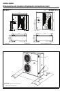
Water connections
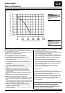
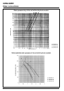
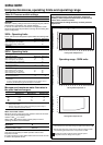
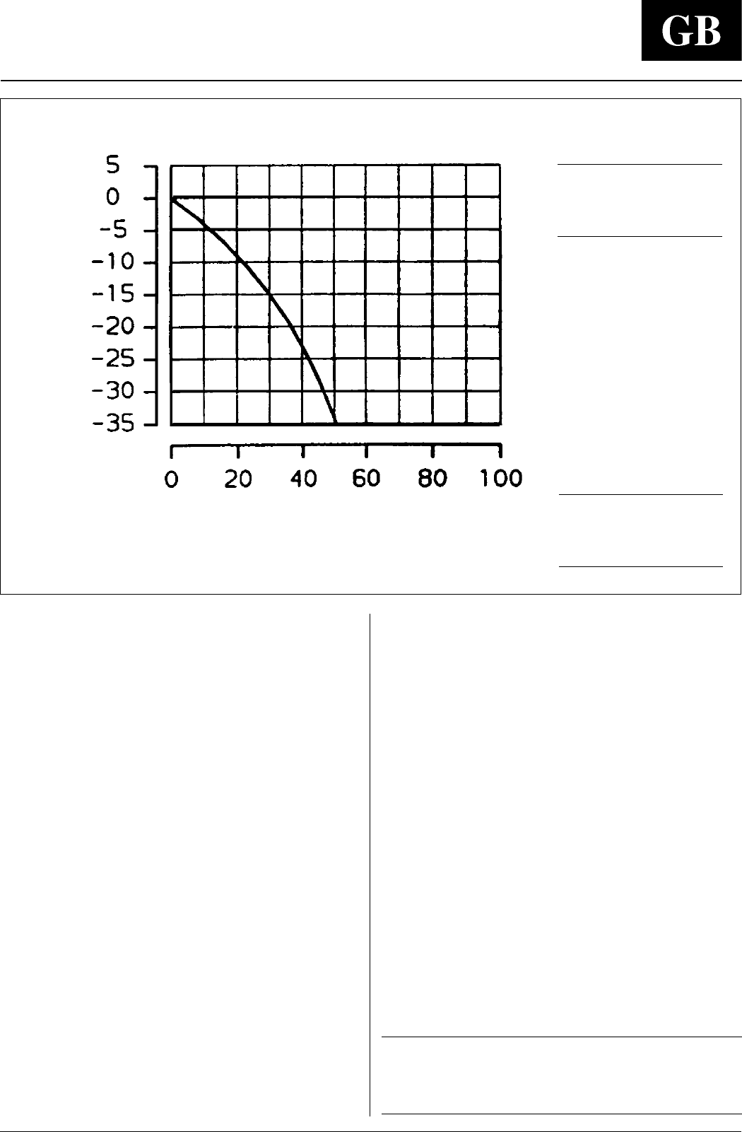
Ethylene glycol curve
Freezing temperature of water- ethylene glycol mixture
°
C
Weight concentration of ethylene glycol in water %
Make the plate heat exchanger hydraulic connections with the
necessary components, using material which will guarantee that
the screwed joints are leakproof.
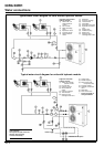
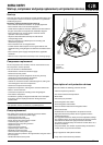
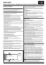
The typical hydraulic circuit diagram shows a typical water circuit
installation in an air conditioning system.
For an application with a water circuit, the following
recommendations must be taken into account:
1. The pump must be fitted immediately before of the heat
exchanger and after the connection to the system return (unit
without hydronic module).
2. It is advisable to install shut-off valves to allow isolation of the
most important circuit components, as well as the heat
exchanger itself.
These valves (ball, globe or butterfly valves) should produce a
minimum loss of charge when they are open.
3. Provide unit and system drains and vents at the lowest system
point.
4. Install purges in the higher sections of the installation.
5. Pressure ports and pressure gauges should be installed
upstream and downstream of the water pump (unit without
hydronic module).
6. Thermometers should be installed in the unit water inlet and
outlet.
7. All piping must be adequately insulated and supported.
Installation of the following components is obligatory:
1. A flow switch should be installed in a straight horizontal stretch
with a length of at least five times the line diameter on either
side.
The flow switch must be positioned in the exchanger inlet pipe.
It must be electrically connected in accordance with the wiring
diagram (only unit without hydronic module).
If this is not possible, the installation should incorporate a
protection device which is activated when there is no water
circulating in the heat exchanger.
2.The presence of particles in the water can lead to obstructions
in the heat exchanger.
It is therefore necessary to protect the heat exchanger inlet with
an extractable mesh filter.
The filter mesh gauge must be at least 10 mesh/cm
2
.
The standard supply of the unit with hydronic module includes a
mesh filter to be fitted during installation.
3.After assembling the system, or repairing the circuit, the whole
system must be thoroughly cleaned with special attention paid
to the state of the filters.
4.Pump flow rate control is made through a flow control valve
supplied with the unit with hydronic module, which must be
installed on the delivery pipe during installation.
5.In case of water refrigeration at temperatures lower than 5°C, or
if the unit is installed in areas where temperatures drop below
0°C, water must be mixed with a proper quantity of ethylene
glycol (see the curve above).
Use the curve to determine the correct ethylene glycol
concentration for the temperature.
Frost protection
The plate heat exchanger and the water connections of the
hydronic module pump may be damaged in spite of the anti-freeze
protection system these units are fitted with.
Frost protection of the plate heat exchanger and of the circuit
inside the hydronic module is always guaranteed down to -10°C
by the electric heaters that are automatically activated if needed.
The power supply to the electric heaters of the plate heat
exchanger and to the internal circuit of the hydronic module must
never be interrupted.
IMPORTANT:
Both the appliance main switch (Q1) and the auxiliary
protection switch for the electric heaters (QF101) must
always be in the closed position (the positions of Q1 and
QF101 are indicated in the wiring diagram).
CAUTION:
Using water with glycol may
make it necessary to change the
configuration of the control
system.
ATTENTION:
The pump leakproof
components are not suitable
for use with propylene
glycol.