


GB - 11
30RA/30RH
ENGLISH
Start-up, compressor and pump replacement, unit protection devices
Start-up
Unit start-up is done by the electronic control described above, and
must always be carried out under the supervision of a qualified air
conditioning engineer.
Necessary checks/precautions before start-up
- Ensure that all electrical connections are properly tightened.
- Ensure that the unit is level and well-supported.
- Check that the hydraulic circuit has sufficient water flow and that
the pipe connections correspond to the installation diagram.
- Ensure that there are no water losses. Check the correct
operation of the valves installed.
- All panels should be fitted and firmly secured with the
corresponding screws.
- Make sure that there is sufficient space for servicing and
maintenance purposes.
- Ensure that there are no refrigerant leaks.
- Confirm that the electrical power source agrees with the unit
nameplate rating, wiring diagram and other documentation for the
unit.
- Ensure that the power supply corresponds to the applicable
standards.
- Make sure that compressors float freely on the mounting springs.
Compressor replacement
As the compressors are hermetic, when an internal fault occurs,
the compressor must be replaced.
This must be done as detailed below:
- Disconnect the unit from the electrical supply.
- Remove the access panels.
- Remove the gas from the refrigerant circuit using recovery
equipment to avoid harming the atmosphere.
- Electrically disconnect the compressor.
- Unbraze or unscrew the suction and discharge lines, taking care
not to damage the rest of the components.
- Remove the compressor fastenings.
- Replace the compressor, ensuring that it contains sufficient oil.
- Braze or screw in the lines.
- Connect the compressor according to the wiring diagram.
- Evacuate the compressor.
- Introduce the quantity of refrigerant indicated on the nameplate
through the service couplings located on the high and low
pressure side.
NOTE:
This operation must be carried out by a qualified person.
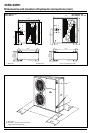
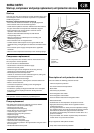
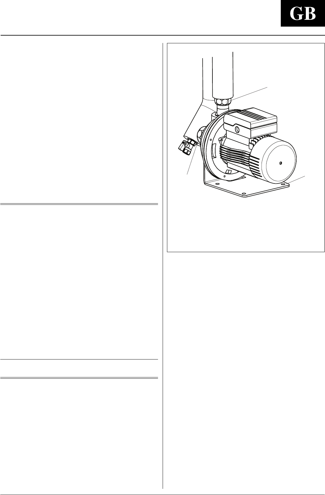
Pump replacement
If the water pump needs to be replaced, proceed as follows:
- Disconnect the unit from the power supply.
- Remove the access panel.
- Electrically disconnect the pump.
- Empty all water from the hydronic module.
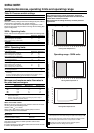
- Loosen the pipe unions a and c.
- Remove the four pump fixing screws b.
- Replace the pump.
- Fit the pump fixing screws b.
- Tighten the pipe unions a and c.
- Electrically connect the pump
- Connect the unit to the power supply
- Make sure the pump rotates in the right direction using the hole in
the back panel.
- Reinstall the lateral access panel.
ቢ
ባ
ቤ
ቢ Pipe union
ባ Screw
ቤ Pipe union
Description of unit protection devices
The unit includes the following protection devices:
- Internal compressor protection.
- Fan motor internal thermal protection.
- Main switch.
- Anti-short-cycle protection.
- Thermomagnetic main switch.
- Thermomagnetic control switch.
- Fans and electric heaters thermomagnetic switch.
- Defrost thermostat.
- Fault detector for the temperature and pressure sensors.
- High pressurestat: this protects the unit against excessive
condensing pressure.
The high pressurestat has factory-fixed non-adjustable settings.
The appliance stops due to the intervention of the high pressure
alarm threshold, before the high pressurestat intervenes.
This function is performed by the electronic control device via a
pressure transducer.
- Low pressurestat: This function is performed by the electronic
control device via a pressure transducer.
Only on appliances with hydronic module
- Pump motor external thermal protection.