


30RA/30RH
GB - 12
Unit protection devices
, operating limits and operating range
Table III: Pressure switch settings
Cut-out Reset
High pressurestat 30 bar Manual
WARNING:
Alteration of factory settings other than the design set-point, without
manufacturer's authorisation, may void the warranty
.
In case of use other than the manufacturer configuration,
Carrier
Service must be asked
for permission to change the Pro-Dialog Plus
system configuration.
30RA - Operating limits
These units have been designed to operate within the following limits:
Evaporator Minimum°C Maximum°C
Water entering temp. (at start-up) 7,8
*
30
Water leaving temp. (in operation) 5** 13
Water entering temp. (at shut-down) - 55
Condenser
Air entering temperature -10 46
30RH - Operating limits
Cooling cycle
Plate heat exchanger Minimum°C Maximum°C
Water entering temp. (at start-up) 7.8
*
30
Water leaving temp. (in operation) 5** 13
Water entering temp. (at shut-down) - 55
Coil
Air entering temperature -10 46
Heating cycle
Plate heat exchanger Minimum°C Maximum°C
Water entering temp. (at start-up) 10 45
Water leaving temp. (in operation) 25 50
Water entering temp. (at shut-down) - 55
Coil Minimum
°C Maximum°C
Air entering temperature -10 20
*
Contact Carrier if an entering water temperature lower than 7.8 °C is
necessary.
**
In case of operation with a leaving temperature of less than 5 °C, it is
necessary to add ethylene glycol to the water in circulation.
Minimum and maximum water flow rates in
the plate heat exchangers
30 RA RH
Minimum flow Maximum flow Maximum flow
rate, l/s rate, l/s* rate, l/s**
017 0,45 1,4 1,3
021 0,57 1,6 1,6
026 0,67 2,1 1,9
033 0,87 2,3 2,4
* Maximum water flow rate with an available static pressure of 50 kPa (units
with hydronicmodule)
** Maximum water flow rate at a plate heat exchanger pressure drop of
100 kPa (units without hydronic module)
Water circuit water content
Whatever the size of the system, the minimum content of the water
circuit is given by the following formula:
Volume = CAP
(kW)
x N = Litres
where CAP is the nominal system capacity (kW) at nominal
operating conditions of the installation.
Application N
Air conditioning 3.5
Industrial process cooling See note
This volume is necessary for stable operation and accurate
temperature control.
It is often necessary to add a buffer water tank to the circuit in order
to achieve the required volume.
NOTE:
For industrial process cooling applications, where high
stability of water temperature levels must be achieved, the
values above must be increased.
We recommend consulting the factory for these particular
applications.
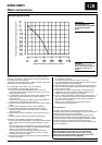
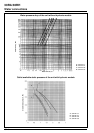
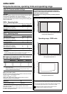
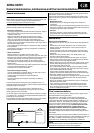
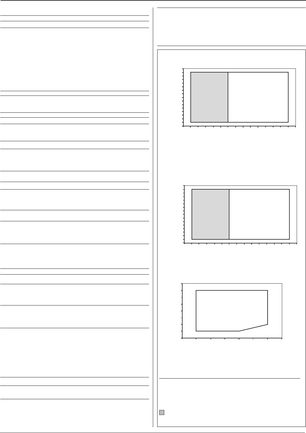
Operating range - 30RA units
Outdoor air temperature
°
C
Operating range - 30RH units
Outdoor air temperature
°
C
Leaving water temperature °C
Notes:
1.
The temperature rise of the water through the plate heat exchanger = 5K.
2. Both the plate exchanger and the circuit inside the hydronic module
are protected against frost down to a temperature of -10°C.
Operating range with anti-freeze solution and with special
configuration of the Pro-Dialog control system.
Leaving water temperature °C
Outdoor air temperature
°
C
Leaving water temperature °C
20
25
30
35
40
45 50
55
-15
-10
-5
0
5
10
15
20
25
-1
0
1
2
3
4
5
6
7
8
91011
12
13 14
-14
-10
-6
-2
2
6
10
14
18
22
26
30
34
38
42
46
50
-1
0
1
2
3
4
5
6
7
8
91011
12
13 14
-14
-10
-6
-2
2
6
10
14
18
22
26
30
34
38
42
46
50