


30RA/30RH
GB - 4
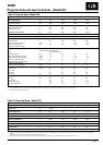
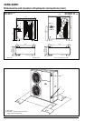
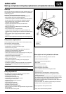
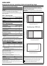
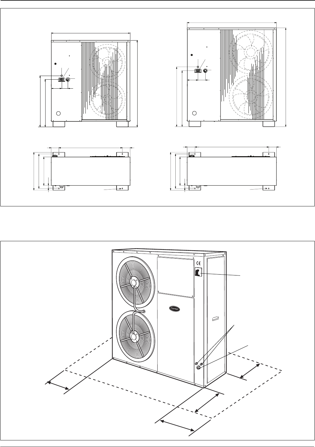
Dimensions and location of hydraulic connections (mm)
200
700
200
400
1. Water inlet 2. Water outlet 3. 3/4” gas safety valve outlet
1
2
3
1328
1453.5
859
796
175 105
12x20
1068
635
130 130
578
478
40
1
2
3
1503
180 125
1003
940
1657.5
1243130 130
635
578
478
40
12x20
Mod. 30RA 017 - 021
Mod. 30RH 017
Mod. 30RA 026 - 033
Mod. 30RH 021 - 026 - 033
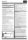
ቢ Main switch
ባ Grommet: 1 Pg 29 and 2 Pg 16 for power
supply and control cables entry
ቢ
ባ
ባ