


22
50XP
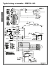
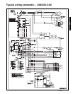
Operating sequence
Cooling — When the system thermostat calls for cooling, 24
V is supplied to the “Y” and “G” terminals of the thermostat.
This completes the circuit to the contactor coil (C) and
indoor (evaporator) fan time delay relay (TDR). The
normally open contacts of C close and complete the circuit
to compressor motor (COMP) and to outdoor (condenser)
fan motor (OFM). Both motors start instantly. The IFM starts
according to the selection pin set-up on the Easy Select™
Board.
On the loss of the thermostat call for cooling, 24 v is
removed from both the “Y” and “G” terminals (provided the
fan switch is in the “AUTO” position) deenergizing the
compressor contactor and opening the contacts supplying
power to compressor/OFM. After preselected delay, the IFM
shuts off. If the thermostat fan selector switch is in the “ON”
position, the IFM will run continuously at speed selected on
Easy Select™ Board.
Heating — If accessory electric heaters are installed, on a
call for heat, circuit R-W is made through the thermostat
contacts. Circuit R-G is made which energizes the IFM. If
the heaters are staged, then the thermostat closes a second set
of contacts (W2) when second stage is required. When
thermostat is satisfied, contacts open, deenergizing the
heater relay. After a preselected delay, the IFM shuts off. If
the thermostat fan selector switch is in the “ON” position,
the IFM will run continuously at speed selected on Easy
Select™ Board.
NOTE: On units with a Time Guard® II device: once the
compressor has started and then stopped, it cannot be
restarted again until 5 minutes have elapsed.
The indoor blower operation with a call for fan operation (G)
in cooling mode will perform by the on/off delay profile
selected at start up on the Easy Select™ Board.
Controls