


2
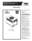
50XP
cooling unit that is pre-wired, pre-
piped, and pre-charged for minimum
installation expense. 50XP units are
available in a variety of standard
cooling sizes with voltage options to
meet residential and light commercial
requirements. Units are light weight,
and install easily on a rooftop or at
ground-level. The hightech, composite
base pan eliminates rust problems
associated with ground level
applications.
Durable, dependable
components
Scroll Compressors
are designed for
high efficiency. Each compressor is
hermetically sealed against
contamination to help promote longer
life and dependable operation.
Vibration isolation provides quiet
operation. Compressors have internal
high-pressure and overcurrent
protection.
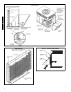
Convertible duct configuration
Unit is designed for easy use in either
downflow or horizontal applications.
Each unit is easily converted from
horizontal to downflow.
Direct-drive variable speed blower
motor
is standard on all 50XP models.
Direct-drive, PSC condenser-fan
motors
are designed to help reduce
energy consumption and provide for
cooling operation down to 55°F outdoor
temperature. Motormaster® II low
ambient kit is available as a field-
installed accessory.
Corporate thermostats
include the
Time Guard® II anti-short cycle
protection circuitry. If a non-Corporate
thermostat without anti-short cycle
protection, is used the Time Guard II
field installed anti-short cycle kit is
recommended.
Refrigerant system
is designed to
provide dependability. Liquid refrigerant
filter driers are used to promote clean,
unrestricted operation. Each unit leaves
the factory with a full Puron® refrigerant
charge. Refrigerant service connections
are standard on the suction and discharge
lines for checking operating pressures.
Thermostatic Expansion Valve
– A
hard shutoff, balance port TXV
maintains a constant superheat at the
evaporator exit (cooling cycle) resulting
in higher overall system efficiency.
Evaporator and condenser coils
are
computer-designed for optimum heat
transfer and cooling efficiency. The
evaporator coil is fabricated from
copper tube and aluminum fins and is
located inside the unit for protection
against damage. The condenser coil is
internally mounted on the top tier of the
unit. Copper fin coils and pre-coated fin
coils are available from the factory by
special order. These coils are
recommended in applications where
aluminum fins are likely to be damaged
due to corrosion. They are ideal for
seacoast applications.
High and Low Pressure Switches
give
added safety and reliability to the
compressor.
Low sound ratings
ensure a quiet
indoor and outdoor environment with
sound ratings as low as 72 dB.
(See page 3.)
Easy to service cabinets
provide easy
single-panel accessibility to serviceable
components during maintenance and
installation. The basepan with
integrated drain pan provides easy
ground level installation with or without
a mounting pad. Convenient handholds
are provided to manipulate the unit on
the jobsite. A nesting feature ensures a
positive basepan to roof curb seal when
the unit is roof mounted. A convenient
3/4-in. wide perimeter flange makes
frame mounting on a rooftop easy.
Louvered Grille
provides hail and
vandalism protection for the coil.
Downflow operation
is easily provided
in the field to allow vertical ductwork
connections. The basepan utilizes
knockout style seals on the bottom
openings to ensure a positive seal in the
horizontal airflow mode.
Cabinets
are constructed of heavy-
duty, phosphated, zinc-coated
prepainted steel capable of
withstanding 500 hours of salt spray.
Interior surfaces of the evaporator and
electric heater compartments are
insulated with cleanable semi-rigid
insulation board, which keeps the
conditioned air from being affected by
the outdoor ambient temperature and
provides improved indoor air quality.
(Conforms to American Society of
Heating, Refrigeration and Air
Conditioning Engineers No. 62P.) The
sloped drain pan minimizes standing
water in the drain, which is provided
with an external drain.
Standard metal duct covers
with
insulation come with the unit and cover
the horizontal duct openings. These can
be left in place if the unit is converted to
downflow.
Table of contents
Page
Features/Benefits. . . . . . . . . . . . . . . . . . . . . . . . . . . . . . . . . . . . . . . . . . . . . . . . . . . . . . . . . . . . . . . . . . . . . . . . . . . . . . . . . . . . . . . . 1,2
Model Number Nomenclature . . . . . . . . . . . . . . . . . . . . . . . . . . . . . . . . . . . . . . . . . . . . . . . . . . . . . . . . . . . . . . . . . . . . . . . . . . . . . . .3
ARI Capacities . . . . . . . . . . . . . . . . . . . . . . . . . . . . . . . . . . . . . . . . . . . . . . . . . . . . . . . . . . . . . . . . . . . . . . . . . . . . . . . . . . . . . . . . . . .3
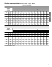
Physical Data . . . . . . . . . . . . . . . . . . . . . . . . . . . . . . . . . . . . . . . . . . . . . . . . . . . . . . . . . . . . . . . . . . . . . . . . . . . . . . . . . . . . . . . . . . . .4
Options and Accessories. . . . . . . . . . . . . . . . . . . . . . . . . . . . . . . . . . . . . . . . . . . . . . . . . . . . . . . . . . . . . . . . . . . . . . . . . . . . . . . . . . 5,6
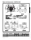
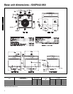
Base Unit Dimensions. . . . . . . . . . . . . . . . . . . . . . . . . . . . . . . . . . . . . . . . . . . . . . . . . . . . . . . . . . . . . . . . . . . . . . . . . . . . . . . . . . . . 7,8
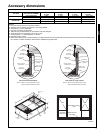
Accessory Dimensions . . . . . . . . . . . . . . . . . . . . . . . . . . . . . . . . . . . . . . . . . . . . . . . . . . . . . . . . . . . . . . . . . . . . . . . . . . . . . . . . . . . . .9
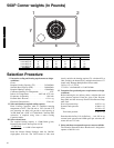
Selection Procedure . . . . . . . . . . . . . . . . . . . . . . . . . . . . . . . . . . . . . . . . . . . . . . . . . . . . . . . . . . . . . . . . . . . . . . . . . . . . . . . . . . . . . .10
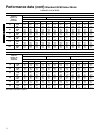
Performance Data . . . . . . . . . . . . . . . . . . . . . . . . . . . . . . . . . . . . . . . . . . . . . . . . . . . . . . . . . . . . . . . . . . . . . . . . . . . . . . . . . . . . . 11-15
Typical Piping and Wiring . . . . . . . . . . . . . . . . . . . . . . . . . . . . . . . . . . . . . . . . . . . . . . . . . . . . . . . . . . . . . . . . . . . . . . . . . . . . . . . . .16
Application Data. . . . . . . . . . . . . . . . . . . . . . . . . . . . . . . . . . . . . . . . . . . . . . . . . . . . . . . . . . . . . . . . . . . . . . . . . . . . . . . . . . . . . . . . .17
Electrical Data. . . . . . . . . . . . . . . . . . . . . . . . . . . . . . . . . . . . . . . . . . . . . . . . . . . . . . . . . . . . . . . . . . . . . . . . . . . . . . . . . . . . . . . .18, 19
Typical Wiring Schematics. . . . . . . . . . . . . . . . . . . . . . . . . . . . . . . . . . . . . . . . . . . . . . . . . . . . . . . . . . . . . . . . . . . . . . . . . . . . . .20, 21
Controls. . . . . . . . . . . . . . . . . . . . . . . . . . . . . . . . . . . . . . . . . . . . . . . . . . . . . . . . . . . . . . . . . . . . . . . . . . . . . . . . . . . . . . . . . . . . . . . .22
Guide Specifications. . . . . . . . . . . . . . . . . . . . . . . . . . . . . . . . . . . . . . . . . . . . . . . . . . . . . . . . . . . . . . . . . . . . . . . . . . . . . . . . . . .23, 24