START-UP
IMPORTANT: Energize crankcase heaters 24 hours prior
to base unit start-up to remove entrapped refrigerant
from the oil. Heaters are energized as long as there is
power to the unit.
Unit Preparation — Make sure that unit has been in-
stalled in accordance with these installation instructions and
applicable codes.
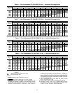
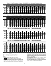
Return-Air Filters — Make sure correct filters are in-
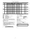
stalled in unit (see Tables 1A and 1B). Do not operate unit
without return-air filters.
Compressor Mounting — Compressors are inter-
nally spring mounted. Do not loosen or remove compressor
holddown bolts.
Internal Wiring — Check all electrical connections in
unit control boxes; tighten as required.
Refrigerant Service Ports — Each refrigerant sys-
tem has 3 Schrader-type service gage ports: one on the suc-
tion line, one on the liquid line and one on the compressor
discharge line. Be sure that caps on the ports are tight.
Cooling — To start unit, turn on main power supply. Set
system selector switch at COOL position and fan switch at
AUTO. position. Adjust thermostat to a setting below room
temperature. Compressor starts on closure of contactor.
Check unit charge. Refer to Refrigerant Charge section on
page 20.
Reset thermostat at a position above room temperature.
Compressor will shut off.
TO SHUT OFF UNIT — Set system selector switch at OFF
position. Resetting thermostat at a position above room tem-
perature shuts unit off temporarily until space temperature
exceeds thermostat setting.
Heating — To start unit, turn on main power supply.
Set thermostat at HEAT position and a setting above room
temperature, fan at AUTO. position.
First stage of thermostat energizes Compressor no. 1 and
Compressor no. 2; second stage energizes the electric heat
(where applicable). Check heating effects at air supply grille(s).
If unit does not energize, reset limit switch (located on
indoor-fan scroll) by depressing button located between ter-
minals on the switch.
TO SHUT OFF UNIT — Set system selector switch at OFF
position. Resetting heating selector lever below room tem-
perature will shut unit off temporarily until the space tem-
perature falls below thermostat setting.
Safety Relief — A soft-solder joint at the suction line
fitting provides pressure relief under abnormal temperature
and pressure conditions.
Ventilation (Continuous Fan) — Set fan and sys-
tem selector switches at ON and OFF positions, respec-
tively. Indoor fan operates continuously to provide constant
air circulation.
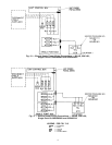
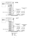
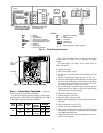
Operating Sequence (See Fig. 20)
COOLING — With accessory economizer — Upon a re-
quest for cooling from the space thermostat, terminals Y1
and G will be energized with 24 v. As a result, the indoor-fan
contactor (IFC), indoor-fan motor (IFM), and reversing valve
solenoids (RVS1 and RVS2) will be energized and the
economizer damper blade will open to minimum position.
Note that if the indoor fan is on when the space thermostat
calls for cooling, terminal G is already energized and the
economizer damper blade is at minimum position.
If the outdoor-air temperature is below the outdoor-air ther-
mostat (OAT) setting, then the position of the damper blade
will be determined by the temperature of the discharge air as
sensed by the discharge-air thermistor (DAT). The damper
blade will slide open for 5 seconds, and rest for 30 seconds
until the proper discharge-air temperature is obtained. The
damper blade will modulate to different positions to main-
tain this discharge-air temperature.
If the thermostat calls for a second stage of cooling
by supplying 24 v to Y2, the outdoor-fan contactor (OFC)
and Compressor contactor no. 1 (C1) will be energized,
which will bring on the outdoor fan and Compressor no. 1,
respectively.
When the thermostat is satisfied, Y2 will be deenergized
first, which will deenergize the outdoor fan and Compressor
no. 1. When the indoor fan is deenergized, the economizer
will return to a fully closed position.
If the outdoor-air temperature is above the OAT setting,
the economizer will move to the minimum position and the
unit will operate as described in Cooling, Units Without
Accessory Economizer section below.
Without accessory economizer — Upon a request for cool-
ing from the space thermostat, terminals Y1 and G will be
energized with 24 v. As a result, the indoor-fan contactor
(IFC), outdoor-fan contactor (OFC) and Compressor con-
tactor no. 1 (C1) will be energized, which in turn will en-
ergize the indoor fan, outdoor fan and Compressor no. 1,
respectively.
If the space thermostat calls for a second stage of cooling
by supplying 24 v to Y2, Compressor contactor no. 2 (C2)
will be energized, thus energizing Compressor no. 2.
When the space thermostat is satisfied, Y2 will be de-
energized first, which will deenergize Compressor no. 2.
Upon a further drop in space temperature, Y1 will be de-
energized which will deenergize Compressor no. 1, and the
outdoor and indoor fans.
HEATING — Upon a request for heating from the space ther-
mostat, terminal W1 will be energized with 24 v. On units
with economizer, the economizer damper blade will move to
minimum position regardless of the outdoor-air tempera-
ture, and the unit will operate as described in Cooling, With-
out Accessory Economizer section above. The IFC, OFC,
C1 and C2 will be energized. The reversing valves switch
position and the indoor fan, outdoor fan, Compressor no. 1,
and Compressor no. 2 are energized.
If the space temperature continues to fall while W1 is en-
ergized, W2 will be energized with 24 v, and the heater con-
tactor(s) (HC) will be energized, which will energize the electric
heater(s).
When the space thermostat is satisfied, W2 will be de-
energized first, and the electric heater(s) will be
deenergized.
Upon a further rise in space temperature, W1 will be de-
energized, and the reversing valve solenoids(RVS1 and RVS2)
will be energized. On units with economizer, the econo-
mizer damper blade will move to the fully closed position.
DEFROST — When the temperature of the outdoor coil drops
below 28 F as sensed by the defrost thermostat (DFT2) and
the defrost timer is at the end of a timed period
(adjustable at 30, 50 or 90 minutes). RVS1 and RVS2 are
energized and the OFC is deenergized. This switches the
17


