


7
V Mounting The Boiler
CAUTIO
N
T
his boiler wei
g
hs approximatel
y
110 pounds
:
• Two people are required to safel
y
lift this boiler onto the wall mountin
g
hook
.
• Make sure that wall mountin
g
hook is anchored to a structure capable of
supportin
g
the wei
g
ht of the boiler and attached pipin
g
when fi lled with water.
Jurisdictions in areas sub
j
ect to earthquakes ma
y
have special requirements
f
or supportin
g
this boiler. These local requirements take precedence over the
r
e
q
uirements shown below.
A. Wall Mounting
1) If the boiler is installed on a framed wall, minimum acceptable framing is 2 x 4 studs on 16” centers. The boiler
mounting holes are on 16” centers for installation between two studs at the standard spacing. In cases where the boiler
cannot be centered between the studs, or where the studs are spaced closer than 16” apart, the boiler may be anchored to
¾” plywood or horizontal 2 x 4's anchored to the studs.
2) 5/16” x 2” lag screws and washers are provided for mounting this boiler. These lag screws are intended for mounting
the boiler directly onto studs covered with ½” sheet rock. When the boiler is attached to other types of construction,
such as masonry, use fasteners capable of supporting the weight of the boiler and attached piping in accordance with
good construction practice and applicable local codes.
3) Make sure that the surface to which the boiler is mounted is plumb.
4) Before mounting the boiler, make sure that wall selected does not have any framing or other construction that will
interfere with the vent pipe penetration.
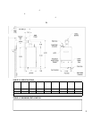
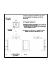
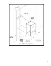
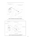
5) Once a suitable location has been selected for the boiler, and any needed modifi cations have been made to the wall, use
Figure 5.1 to locate holes “A” and “B”. Make sure that the horizontal centerline of these holes is level. Holes “C” and
“D” may also be drilled at this time or after the boiler is hung on the wall. If the 5/16 x 2” lag screws are used, drill
3/16” pilot holes.
6) Cut the opening/s in the wall for the vent system. The recommended hole diameter for the standard 60/100mm coaxial
vent pipe is 4-3/8”.
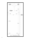
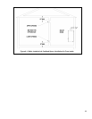
7) Attached the wall hanging hook using the 5/16” x 2” lag screws and washers, or other suitable anchors as appropriate
(Figure 5.2). Make sure the hook is level.
8) Hang the boiler on the wall hook as shown in Figure 5.2.
9) If not already done in Step (4) locate and drill holes “C” and “D” using the ob-round slots in the bottom mounting
fl ange. Secure the bottom fl ange to the wall using the 5/16" x 2” lag screws, or other fasteners as appropriate (Figure
5.2).
10) Verify that the front of the boiler is plumb. If it is not, install washers at holes “C” and “D” between the bottom
mounting fl ange and the wall to adjust.
11) See Section VII (“Venting) for instructions on attaching the vent system to the boiler.
B. Floor Mounting
This boiler may be mounted on the fl oor using an optional pedestal kit available from U.S. Boiler. Follow the
instructions provided with this kit to assemble the pedestal, and attach it to the boiler. When this pedestal is used, the
boiler may be installed directly on a non-carpeted combustible fl oor.