79
14; Parameter 13 denes the “thousands” and
hundreds” places and Parameter 14 denes the
“tens” and “ones” places. The ignition fan speed
is only adjustable in increments of hundreds, so
only one parameter (19) is required to dene it.
IMPORTANT: Field adjustment of fan speeds is
not recommended.
b. In some cases one two-digit number denes two
separate parameters. For example, if Parameter
34 is viewed on the boiler display, the “tens
place” is Parameter 34-1 (default value is 0) and
the “ones place” is Parameter 34-2 (default value
is also 0). As viewed on the boiler display, the
factory set Parameter 34 will therefore appear as
“00”. If Parameters 34-2 is changed to accept a
0-10 VDC reading from an AM-4 (see Section
D), Parameter 34 will then read “04” as viewed
on the boiler display.
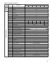
Common Field Adjustments
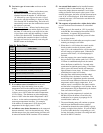
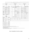
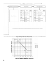
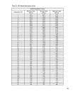
Please note that although it is physically possible to
adjust all parameters listed in Table 25 the parameters
shaded gray need not be adjusted in the eld. In case
these parameters are accidentally changed, they should
be restored to default factory settings shown in Table 25
“Parameter Descriptions”.
Parameters permitted to be eld adjusted are non-
shaded ones in Table 25. In order to change these
parameters, three subsequent tasks must be performed:
1. Adjusting the target boiler supply temperature when
responding to call from an indirect water heater -
The default IWH target supply temperature is 180°F.
Since most indirect water heaters have ratings based
on 180°F boiler supply temperature, it should rarely
be necessary to adjust this parameter.
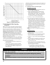
2. Changing the boiler water reset curve - When an
outdoor temperature sensor is connected to a Alpine
boiler, the MCBA will adjust the target boiler supply
temperature based on outdoor temperature when
the boiler is responding to a call for central heat.
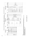
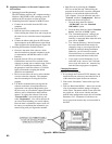
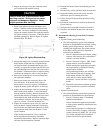
Figure 53 is a graph showing the target boiler supply
temperature as a function of outdoor temperature.
The curve shown in Figure 53 is that obtained with
the factory set parameters. The shape of this curve
may be changed by changing Parameters 4, 5, 6, and
7 as shown in Figure 53. Refer to Part I Section C
for the procedure to change parameters.
If the outdoor sensor is not connected to the boiler,
the target supply temperature is always dened
by Parameter 4 when the boiler is responding to
a call for central heat, regardless of the outdoor
temperature. In this case, the settings of Parameters
5, 6, and 7 are meaningless.
3. Allowing an external control to directly manage
modulation of the boiler. The MCBA control
permits the Alpine to be modulated solely using 0 -
10 VDC signal supplied by an external control,
like multiple - modulating boiler control. When this
function is used, the boiler no longer responds to a
heating thermostat, or an outdoor sensor connected
to a boiler MCBA itself. The boiler will respond
normally to the call from the domestic hot water
thermostat.
In order for the boiler MCBA control to
recognize 0 - 10 VDC signal, Parameter 34-2
(“Room Thermostat” - see Table 25) must be
re-programmed. The factory programmed
default value for Parameter 34 is “0”. It must
be re-programmed to value “4” for MCBA to
recognize 0 - 10 VDC signal. Once this parameter
is changed, the boiler will ignore any call from a
thermostat connected across boiler terminals 1 and 2
(see Figures 35 and 36). It will continue to respond
to a call from the indirect water heater thermostat.
Also, Parameters 2 and 3 (see Table 25) should
be left at factory settings they could be changed
inadvertently (for example, pushing and holding
“+” or “-” key while boiler is in Standby Mode
will change them). If the boiler does not respond
to a call from one or both thermostats, verify that
Parameters 2 and 3 are both “ON”.
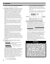
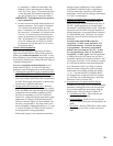
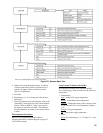
4. Communication, Fan Speed and Error Modes
In addition to providing access to all eld adjustable
parameters, entering the access code also provides
access to three additional mode menus using the
boiler keypad. These are shown in Figure 52:
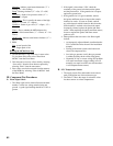
a. Communication Mode - This mode does not
currently have any function.
b. Fan Speed Mode - Allows the user to view the
blower fan speed (ring rate is determined by fan
speed).
c. Error Mode - Pressing STEP while in Error mode
allows the user to see the six most recent error
codes.


