23
i. Install the supplied Inside Wall Plate onto the
shortened Horizontal (Wall) Terminal interior
end and move the plate to cover interior wall
cut opening. Secure the plate with provided
fasteners, then, apply the sealant around plate
sides to seal it to interior wall.
j. Lubricate the brown gasket inside boiler
concentric vent collar or the last section of the
vent pipe with small amount of water.
k. Ensure that inner pipe of the terminal is evenly
engaged into the gasket all around, then push the
termination male end inside boiler concentric
vent collar or the last section of the vent pipe,
until the mark (see Step g) is no longer visible.
l. Re-install locking band clamp onto the joint
to secure the terminal to the collar or the last
section of the vent pipe.
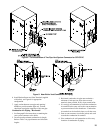
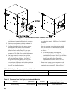
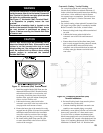
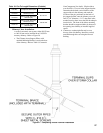
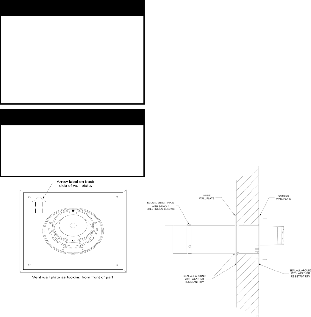
Figure 17: Horizontal (Wall) Terminal Detail
WARNING
The terminal vent portion is offset towards the top
inside the outer pipe of the Horizontal Concentric
Vent Terminal to provide vent pipe pitch towards
the boiler for condensate removal.
See Figure 17 ‘Horizontal (Wall) Terminal Detail’.
It is imperative to properly mount the vent
terminal.
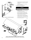
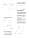
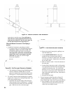
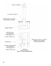
The terminal orientation label is located on the
inside of the terminal Outside Wall Plate. Insure
the vent terminal is positioned as shown in
Figure 18 before securing the Outside Wall Plate
to exterior wall.
CAUTION
Exterior wall surface must be reasonably at to
attach the Outside Wall Plate. When exterior wall
surface is not at (covered with vinyl or wood
shingle siding etc.) the siding must be removed,
and a at surface build up ash or above siding
exterior surface to secure/seal the terminal
Outside Wall Plate.
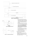
Figure 18: Completing Horizontal (Wall)
T
erminal Installation
Concentric Venting - Vertical Venting
For vertical (through the roof) venting, extend
Vertical (Roof) Terminal to maintain minimum 12
inches vertical and horizontal distance from building
roof surface. Allow additional vertical distance
for expected snow accumulation. Provide brace as
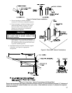
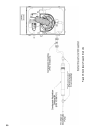
required. See Figure 19 ‘Vertical Concentric Vent
Installation’.
1. For vertical venting, where optional Concentric Vent
90° degree long radius elbow is attached to installed
Boiler Concentric Vent Collar, to install elbow:
a. Remove locking band clamp off the terminal and
set aside.
b. Lubricate the brown gasket inside boiler
concentric vent collar with small amount of
water.
c. Ensure that male end of the elbow inner plastic
pipe is evenly engaged into the gasket all around,
then, push the elbow male end inside boiler
concentric vent collar until the bead on male end
of elbow outer pipe bottoms out inside boiler
vent collar.
d. Re-install locking band clamp onto the joint to
secure the elbow to the collar.
e.
Continue installing additional concentric vent
cuttable or non-cuttable piping as required.
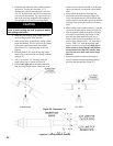
2. Additionally, secure elbow to boiler vent collar with
three evenly spaced #8 x ½” sheet metal screws.
Use collar rivets as reference attachment points.
Mark (center punch) each screw location off each
rivet centerline 5/8” towards collar-beaded end. See
Figure 18 ‘Completing Horizontal (Wall) Terminal
Installation’ for details. Drill 1/8” hole thru both


