22
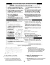
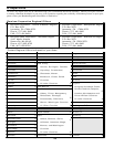
Table 7: Pilot Burner Location
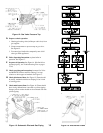
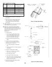
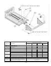
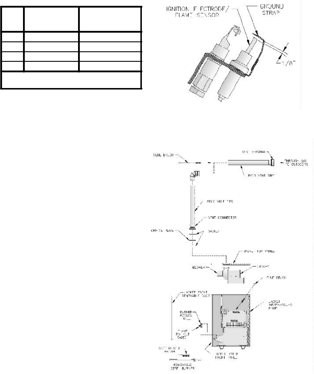
Figure 18: Spark Gap Setting
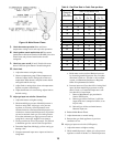
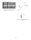
Figure 19: Flueway Cleaning
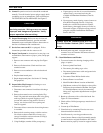
at rear of burner. See Figure 11. Slide burner
over orifice.
7. Reconnect pilot gas supply, igniter/sensor
cable, and ground wire. Reinstall Burner
Access Panel. Reconnect Flame Rollout
Switch wires.
G. Check operation. Follow Paragraphs D through
O from Section VII: System Start-up.
H. Removal or replacement of pilot assembly or
pilot assembly parts. If pilot assembly, sensor or
pilot orifice need replacing, remove main burner
with pilot using procedure described in
Paragraph F.1.
1. To replace orifice.
a. Disconnect pilot tubing. Pilot orifices
screw into Pilot Burner. Replace with
Honeywell 388146NE (Natural Gas) or
Honeywell 388146KP (LP/Propane).
b. Reconnect pilot tubing and check for
leaks.
2. To adjust or check spark gap between
electrode and hood on Honeywell Q348A
intermittent pilot. See Figure 18.
a. Use round wire gauge to check spark
gap.
b. Spark gap should be 1/8 inch for optimum
performance.
3. To replace complete pilot assembly.
a. Remove two machine screws holding
pilot burner to pilot bracket.
b. Disconnect pilot tubing.
c. Disconnect all other leads to pilot.
d. Select pilot assembly with identical model
number, reconnect leads and pilot tubing.
Resecure to pilot bracket.
4. Reinstall main burner following procedure
described in Paragraph F.
Boiler
Model
Main Burner with
60° Pilot Bracket *
Pilot Burner Located
Between Main
Burners *
203PV 1 1 & 2
204PV 2 2 & 3
205PV 3 3 & 4
206PV 4 4 & 5
* Main burners numbered left to right as viewed from
front of boiler.


