


15
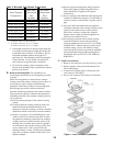
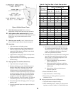
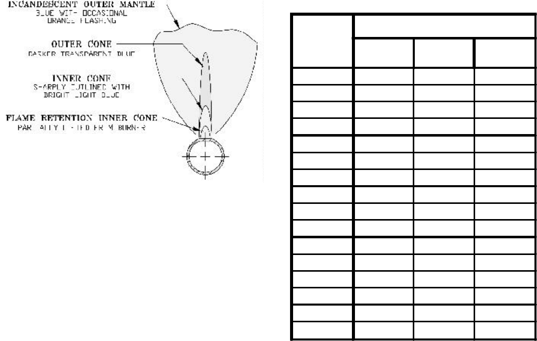
Figure 16: Main Burner Flame
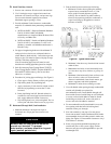
J. Check thermostat operation. Raise and lower
temperature setting to start and stop boiler operation.
K. Check ignition control module shut-off. Disconnect
igniter/sensor cable from Terminal 9 (SPARK). Gas valve
should close and pilot and main burners should
extinguish.
L. Check low water cut-off (if used). Drain boiler water
below LWCO set point. Burners should extinguish.
M. Check limit.
1. Adjust thermostat to highest setting.
2. Observe temperature gauge. When temperature is
indicated, adjust limit to setting below observed
temperature. Main burners and pilot burner should
extinguish and blower stop.
3. Adjust limit to setting above observed temperature.
Ignition sequence should begin.
4. Adjust thermostat to lowest setting. Adjust limit to
desired setting.
N. Adjust gas input rate to boiler (Natural Gas).
1. Adjust thermostat to highest setting.
2. Check manifold gas pressure. Manifold pressure is
listed on rating label. Adjust gas valve pressure
regulator as necessary (turn adjustment screw
counterclockwise to decrease manifold pressure, or
clockwise to increase manifold pressure). If pressure
can not be attained, check gas valve inlet pressure.
If less than minimum gas supply pressure listed on
rating label, contact gas supplier for assistance.
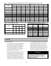
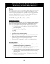
3. Clock gas meter for at least 30 seconds. Use Table 6
to determine gas flow rate in Cubic Feet per Hour.
4. Determine Input Rate. Multiply gas flow rate by gas
heating value.
5. Compare measured input rate to input rate listed on
rating label.
Table 6: Gas Flow Rate in Cubic Feet per Hour
a. Boiler must not be overfired. Reduce input rate
by decreasing manifold pressure. Do not reduce
more than 0.3 inch w.c. If boiler is still overfired,
contact your Burnham distributor or Regional
Office for replacement Gas Orifice.
b. Increase input rate if less than 98% of rating label
input. Increase manifold gas pressure no more
than 0.3 inch w.c. If measured input rate is still
less than 98% of rated input:
i. Remove Main Burners per procedure in
Section VIII: Service.
ii. Remove gas orifices. Drill one (1) drill size
larger (drill size is stamped on orifice, or see
Key No. 4D).
iii. Reinstall gas orifices and main burners.
Measure input rate.
6. Recheck Main Burner Flame.
7. Adjust thermostat to normal setting.
8. Return other gas-fired appliances to previous
conditions of use.
O. Adjust gas input rate to boiler (LP/Propane).
1. Adjust thermostat to highest setting.
2. Check manifold pressure. Adjust gas valve pressure
regulator to obtain 10 inches w.c. manifold pressure.
Seconds
for One
Revolution
Size of Gas Meter Dial
One-Half
Cu. Ft.
One
Cu. Ft.
Two
Cu. Ft.
30 60 120 240
32 56 113 225
34 53 106 212
36 50 100 200
38 47 95 189
40 45 90 180
42 43 86 172
44 41 82 164
46 39 78 157
48 37 75 150
50 36 72 144
52 35 69 138
54 33 67 133
56 32 64 129
58 31 62 124
60 30 60 120