


11
D. Install Vent Pipe, General.
1. Start at vent connector. Work toward vent terminal.
2. Use ¾ inch pipe strap to support horizontal runs,
maintain vent location and slope, and prevent sags.
Do not restrict thermal expansion movement.
Maximum support spacing is 5 feet.
3. Provide minimum 5 inch clearance to combustible
materials. Use thimble when penetrating combustible
wall.
a. 203PV and 204PV - Single wall thimble, Burnham
Part No. 8116116. Other wall thimble
manufacturers are American Metal Products, Hart
& Cooley, and Metal Fab.
b. 205PV and 206PV - Double wall thimble, Burnham
Part No. 8116115 (accomodates 5" to 8¾" wall
thickness). Another wall thimble manufacturer is
Hart & Cooley.
4. Cut pipe to length using hacksaw with minimum 32
teeth per inch or circular saw with metal abrasive
wheel. Remove bead end only - bell end accepts next
fitting or pipe. Cut must be square with pipe. Scrape
off burrs with sharp edged tool.
Note: If remaining pipe (less bell) must be used,
beaded end of mating pipe/fitting must be crimped.
5. Seal all joints using Dow Corning Silastic 732 RTV,
Dow Corning Silastic 736 RTV, Polybac #500 RTV, or
Sil-bond RTV 4500 (Acetoxy). Do not use other
adhesives or sealants.
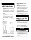
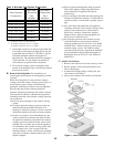
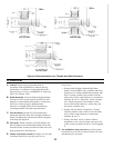
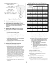
6. Procedure for joining pipe and fittings. See Figure 8.
a. Clean pipe or fitting. Remove all dirt and grease.
b. Slip locking band over pipe/fitting bell.
c. Apply continuous ¼ inch bead of sealant around
bead end of pipe/fitting no more than
1
/8 inch
from end.
d. Insert pipe/fitting into bell. Smooth sealant for
continuous seal around gap between bead and
bell. Apply additional sealant if necessary.
e. Slip locking band over joint and tighten. Do not
secure joint with sheet metal screws or pop rivets.
E. Horizontal (Through Wall) Vent Installation.
1. Maintain minimum ¼ inch per foot slope in
horizontal runs. Slope pipe down toward vent
terminal.
CAUTION
Moisture and ice may form on surfaces
around vent terminal. To prevent
deterioration, surfaces should be in good
repair (sealed, painted etc.)
2. Vent terminal location restricted per following:
a. Minimum 12 inches above grade plus normally
expected snow accumulation level, or 7 feet
above grade if located adjacent to public
walkway. Do not install over public walkway
where local experience indicates condensate or
vapor from Category III appliances creates a
nuisance or hazard.
Figure 8: Typical Joint Detail
b. Minimum 3 feet above any forced air inlet located
within 10 feet.
c. Minimum 4 foot below, 4 foot horizontally from,
or 1 foot above any door, window, or gravity air
inlet.
d. Minimum 4 feet horizontally from, and in no case
above or below, unless a 4-foot horizontal
distance is maintained, from electric meters, gas
meters, regulators and relief equipment.
e. Minimum 12 inches from overhang or corner.
3. Use wall thimble when passing through combustible
outside wall (thimble use optional for
noncombustible wall). Insert thimble through wall
from outside. Secure outside flange to wall with nails
or screws, and seal with adhesive material. Install
inside flange to inside wall, secure with nails or
screws, and seal with adhesive material.
4. For noncombustible wall when thimble is not used,
size opening such that bell with locking band
attached cannot pass through.
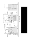
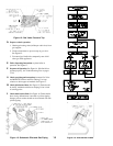
5. Join vent terminal to vent pipe. Cut vent pipe to
locate vent terminal 3 inches (minimum) and 6 inches
(recommended) from wall when joined to inside vent
piping. See Figure 9. Vent terminal clearance to vinyl
wall surfaces is 6 inches.
6. Insert vent pipe through thimble/opening from
outside and join to vent system. Apply sealant
between vent pipe and opening/thimble to provide
weathertight seal.