IX. REMOTE TEMPERATURE SENSOR
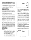
A remote temperature sensor is available to read the tem-
perature from a space. If a remote temperature sensor is
connected, the thermostat will ignore the reading of its in-
ternal sensor. When the thermostatis usinga readingfrom
a remote sensor, the degree symbol above the tempera-
ture reading will blink.
X. KEYPAD LOCK
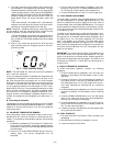
To prevent unauthorized use of the thermostat, the front
panel buttons can be disabled. To disable or lock the
keypad, press and hold the Mode button. While holding
down the Mode button, press the UP and DOWN ARROW
buttons simultaneously. The ‘‘Locked’’ icon will appear on
the display.
The thermostat is unlocked by performing the same pro-
cedure. Press and hold the Mode button. While holdingdown
the Mode button, press the UP and DOWN ARROW but-
tons simultaneously. The ‘‘Locked’’icon will be removed from
the display.
TROUBLESHOOTING
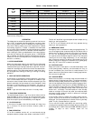
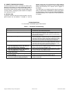
For thermostat troubleshooting see Table 4 below.
Table 4 — Thermostat Troubleshooting
PROBLEM SOLUTION
Display on thermostat not illuminated. Check for 24 vac at the R terminal connection. Terminal R must be
connected for proper thermostat operation.
‘‘Service Filter’’ is displayed on thermostat. After the configured number of blower operating hours, the Service
Filter message will be displayed. This reminds the owner to re-
place the filter. Reset the Service Filter feature to reset the blower
operation timer to 0 hours.
Cooling will not energize. Select COOL mode. Decrease cooling set point to 10 degrees be-
low room temperature. Check for 24 vac at Y1 terminal. If present,
thermostat is operatingcorrectly and problemis with wiring orequip-
ment. If 24 vac is not present, replace the thermostat. Check for
Compressor Cycle per Hour Limit. Cooling may be locked out.
Heating will not energize. Select HEAT mode.Increase heating set pointto 10 degrees above
room temperature. Check for24 vac at W1/O/B terminal.If present,
thermostat is operatingcorrectly and problemis with wiring orequip-
ment. If 24 vac is not present, replace the thermostat.
When using4 wires (R,G,W,Y), thecooling equip-
ment tries repeatedly to turn on, but cannot. At
times the display dims or disappears.
There is not enough power available. Connect a 270 ohm, 10 watt
power resistor at the air-conditioning equipment between terminals
W and C (non-heat pump applications only).
When using4 wires (R,G,W,Y), theheating equip-
ment tries repeatedly to turn on, but cannot. At
times the display dims or disappears.
There is not enough power available. Connect a 270 ohm, 10 watt
power resistor at the air-conditioning equipment between terminals
Y and C (non-heat pump applications only).
When controlling a heat pump, heat comes on
during cooling cycle.
Configure thermostat for heat pump operation (Table 2, Step 3).
When calling forcooling, both heating andcool-
ing are energized.
The thermostat is configured for a heat pump. Configure the ther-
mostat for non-heat pump operation (Table 2, Step 3).
When controlling a commercial heat pump unit,
unit runs in reverse or heating is always on.
Commercial heat pumps require that Heat Pump Option on ther-
mostat is turned OFF.
Copyright 1998 Bryant Heating& Cooling Systems CATALOG NO.809-684Printed in U.S.A.


